background image

Important Safety Instructions

WARNING:

To avoid fire, shock and serious personal injury, follow these instructions.

1. Read your owner’s manual and safety information before installing your new fan. Review the accompanying assembly

diagrams.

2. Before servicing or cleaning unit, switch power off at service panel and lock service panel disconnecting means to prevent

power from being switched on accidentally. When the service disconnecting means cannot be locked, securely fasten a
warning device, such as a tag, to the service panel.

3. Be careful of the fan and blades when cleaning, painting, or working near the fan. Always turn off the power to the ceiling

fan before servicing.

4. Do not insert anything into the fan blades while the fan is operating.

Additional Safety Instructions

1. To avoid possible shock, be sure electricity is turned off at the fuse box before wiring, and do not operate fan without

blades.

2. All wiring and installation procedures must satisfy National Electrical Codes (ANSI/ NFPA 70) and Local Codes. The

ceiling fan must be grounded as a precaution against possible electrical shock. Electrical installation should be made or
approved by a licensed electrician.

3. The fan base must be securely mounted and capable of reliably supporting at least 35 lbs. (fan and accessories not to

exceed 35 lbs. or 15.88 kgs.). See page 5 of owner’s manual for support requirements. Consult a qualified electrician if in
doubt.

4. The fan must be mounted with the fan blades at least 7 feet from the floor to prevent accidental contact with the fan blades.
5. Follow the recommended instructions for the proper method of wiring your ceiling fan. If you do not have adequate

electrical knowledge or experience, have your fan installed by licensed electrician.

6. Suitable for use with solid-state speed controls.

WARNING:

This pr

WARNING: 

TO REDUCE THE RISK OF SHOCK, THIS FAN MUST BE INSTALLED WITH A GENERAL USE ISOLATING WALL 

CONTROL/SWITCH.

oduct is designed to use only those parts supplied with this product and/or accessories designated

specifically for use with this product. Using parts and/or accessories not designated for use with this product could result in
personal injury or property damage.

WARNING:

To reduce the risk of personal injury, do not bend the blade bracket (flange or blade holder) when installing the

brackets, balancing the blades, or cleaning the fan. Do not insert foreign objects in between rotating fan blades.

LIMITED LIFETIME WARRANTY

2. ONE YEAR MOTOR LABOR WARRANTY - If your fan motor fails at any time within one year from the original purchase, due

to defects in materials or workmanship, labor to repair the motor will be provided free of charge at our national service
center. Purchaser will be responsible for labor charges after this one-year period. Customer shall be responsible for all
costs incurred in the removal or reinstallation and shipping of the product for repairs or replacement.

3. If any other part of your fan fails at any time within one year after original purchase, due to a defect in materials or

workmanship, we will repair, or replace, at our option, the defective part free of charge for parts and labor performed at our
national service center.

4. Because of varying climate conditions, this warranty does not cover changes in the finish, including rusting, pitting,

corroding, tarnishing, or peeling.

5. This warranty is void and does not apply to damage from improper installation, neglect, accident, misuse, exposure to

extremes of heat or humidity, or as a result of any modification to the original product.

5. The appliance is not intended for use by young children or infirm persons without supervision. Young children should be 

supervised to ensure that they do not play with the appliance.

7. This fan is to be used in dry location only.

5.   Do not operate reversing switch until fan blades have come to a complete stop.

8. For supply connections, if the conductor of a fan is identified as a grounded conductor, then it should be connected to a 
grounded conductor power supply. If the conductor of a fan is identified as an ungrounded conductor, then it should be 
connected to an ungrounded conductor power supply. If the conductor of a fan is identified for equipment grounding, then it 
should be connected to an equipment grounding conductor.

10. A certain amount of wobble is normal and should not be considered a problem or a defect.

Extends to the original purchaser of 

our

 Fan

1. LIMITED LIFETIME MOTOR WARRANTY - If any part of your fan motor fails, due to a defect in materials or workmanship

during the lifetime of the original purchaser, 

we

 will provide the replacement part free of charge, when the defective fan is 

returned  to  our  national  service  center.  Proof  of  purchase  is  required.  Customer  shall  be  responsible  for  all  costs
incurred in the removal or reinstallation and shipping of the product for repairs or replacement.

7.

We

 reserve  the  right  to  modify  or  discontinue  any  product  at  any  time  and  may  substitute  any  part  under  this

warranty.

6. All costs of removal and reinstallation of the fan are the sole responsibility of the owner of the fan and not the store that

sold the fan or 

us

.

8. Under  no  circumstances  may  a  fan  be  returned  without  prior  authorization  from  

us

.  The  receipt  of  purchase  must

accompany authorized returns and  must  be  sent  freight  prepaid  to 

us

.  The  fan  to  be  returned  must  be  properly packed 

to avoid damage in transit; 

We

 will not be responsible for any damage resulting from improper packaging.

9. It  is  understood  that  any  repair  or  replacement  is  the  exclusive  remedy  available  from  

us

.  There  is  no  other

expressed or implied warranty. 

We

 hereby disclaim any and all implied warranties, including, but not limited to those of

 merchantability  and  fitness  for  a  particular  purpose  to  the  extent  permitted  by  law.  Some  states  do  not  allow
limitations on implied warranties. 

We

 will not be liable for incidental, consequential, or special damages arising out of or in 

conjunction with product use or performance, except as may otherwise be accorded by law. This warranty gives you special
 legal rights and you may also have other rights that vary from state to state.

Summary of Contents for Teolo

Page 1: ...19 CEILING FAN Serial Number Purchase Date Net Weight 21 23 lbs 9 63 kg Questions problems missing parts Before returning to your retailer call our customer service department READ AND SAVE THESE INS...

Page 2: ...e within one year after original purchase due to a defect in materials or workmanship we will repair or replace at our option the defective part free of charge for parts and labor performed at our nat...

Page 3: ...ing Fan 7 How to Hang Your Ceiling Fan 9 How to Wire Your Ceiling Fan How to Install Your Canopy Housing How to Assemble Your Ceiling Fan Blades How to Assemble Your Light Kit How to Operate Your Ceil...

Page 4: ...edge or experience have your fan installed by a licensed electrician WARNING p to ft ft Materials iring outlet o and o connectors ust e of type re uired y the local code he ini u wire would e a conduc...

Page 5: ...volts AC 60 HZ 15 Amp Circuit Electrical code requires use of a fan rated outlet box to support the extra weight and motion associated with a ceiling fan A fan rated box will be labeled as such and t...

Page 6: ...reduce the risk of fire electrical shock or personal injury mount fan to outlet box marked acceptable for fan support of 15 88 kg 35 lbs or less Use screws supplied with outlet box Most outlet boxes...

Page 7: ...pin with hairpin clip Tighten the two set screws with nuts in the downrod support Figure 4 WARNING It is critical that the clevis pin in the downrod support is properly installed and the set screws an...

Page 8: ...canopy Figure 7 Route the black white and blue wires through the hanger ball Position the pin through the two holes in the downrod and align the hanger ball so the pin is captured in the groove in th...

Page 9: ...between the hanger ball assembly and the hanger bracket 1 Securely attach the hanger bracket to the outlet box not included using the outlet box screws and washers supplied with the outlet box Figure...

Page 10: ...leads upward and carefully push leads into the outlet box with the white and green leads to one side of the box and the black leads to the other side Figure 4 CAUTION INCORRECT WIRE CONNECTION WILL D...

Page 11: ...e electrical wires are completely inside the canopy housing and not pinched between the housing and the ceiling NOTE This step is applicable after the neccessary wiring is completed Canopy Screw Cover...

Page 12: ...inside the adaptor plate at the bottom of the motor assembly Slightly loosen the remaining two screws Assemble the light plate assembly to the adaptor plate of the motor assembly using the two keyslot...

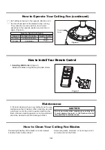
Page 13: ...To make fan operational install 23A 12V battery included in hand held remote transmitter with fan power off Then follow the remote code setting process If not used for long periods of time remove batt...

Page 14: ...or harsh rags which can warp and ruin the finish 1 Periodic cleaning of your new ceiling fan is the only maintenance that is needed When cleaning use only a soft brush or lint free cloth to avoids cr...

Page 15: ...hed to fan 2 Loose screws in motor housing 4 Wire connectors inside housing rattling 5 Motor noise caused by solid state variable speed control 3 FAN WOBBLES EXCESSIVELY 1 Tighten both setscrews secur...

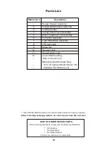
Page 16: ...Insert FINISH CODES Refer to fan model number located on downrod support Reference Description 1 2 3 4 Motor Coupling Cover Assembly 5 Light Plate Glass Assembly LED Assembly Blade Set Receiver Unit H...

Page 17: ...7 NOTE The illustration shown is not to scale or its actual con guration may vary Product parts are subject to change without notice Figure 1 12 12 1 12 2 3 4 5 6 9 7 8 10 11 Exploded View Illustratio...

Page 18: ...TAS INSTRUCCIONES N mero de serie Fecha de compra Peso neto 9 63 kg 21 23 lbs VENTILADOR DE TECHO Preguntas problemas piezas faltantes Antes de volver a la tienda llame a nuestro Departamento de Servi...

Page 19: ...icista calificado Las aspas del ventilador deben instalarse por lo menos a 2 13 m 7 pies del suelo a fin de evitar un contacto accidental con las mismas 4 Siga las recomendaciones sobre el m todo corr...

Page 20: ...n contacto con su proveedor local Materiales tama o del cable seg n el A W G Calibre de Alambre Estadounidense longitud del cable instalado 14 12 hasta 15 2 m 50 pies de 15 2 a 30 5 m 50 a 100 pies Cu...

Page 21: ...epresentamosalgunassugerencias para asegurar un rendimiento eficiente del producto Apague el ventilador cuando no se encuentre en la habitaci n Los ventiladores son para refrescar a la gente no a las...

Page 22: ...pagar el interruptor de pared no es suficiente Para evitar posibles descargas el ctricas aseg rese de que la electricidad est desconectada en la caja de fusibles principal antes de realizar la instala...

Page 23: ...soporte para techo a trav s de la varilla Figura 3 4 Enrosque el soporte de la varilla y alinee los orificios 5 Retire los dos tornillos en el ensamble del motor y gu rdelos para despu s Figura 5 de...

Page 24: ...a extremo del cable Figura 9 NOTA Se deben revisar todos los tornillos de fijaci n y volver a ajustarlos cuando sea necesario antes de realizar la instalaci n 8 Vuelva a colocar la semiesfera en el ba...

Page 25: ...olgar y la abrazadera para colgar ADVERTENCIA ADVERTENCIA Para evitar una posible descarga el ctrica aseg rese de cortar la alimentaci n el ctrica de la caja de fusibles principal antes de colgar el v...

Page 26: ...el ventilador con el conector de cables incluido con la unidad receptora Conecte el conductor negro de la unidad receptora marcado TO MOTOR L al conductor negro del ventilador con el conector de cable...

Page 27: ...Figura 1 ADVERTENCIA 2 Coloque y ajuste firmemente la cubierta para el tornillo de la base sobre los tornillos de reborde de la abrazadera para colgar mediante el mecanismo de seguro por giro del chav...

Page 28: ...apriete tres los tornillos Figura 1 2 Retire uno de los tres tornillos en del ensamble de 3 Afloje levemente los otros dos tornillos Instale el conector 2 de pasadores desde unidad de luz LED conexi...

Page 29: ...idad del mando a distancia del ventilador de techo C mo utilizar su ventilador de techo 3 Para que el ventilador sea functional instale las pila continuaci n siga el proceso de fijaci n remota de c di...

Page 30: ...ventilador y la iluminaci n se apagar n tras 6 hora Enciende el ventilador y aumenta la velocidad Enciende el ventilador y disminuye la velocidad Enciende el ventilador y aumenta la velocidad 6 Si des...

Page 31: ...mero Limpieza de las aspas Evite usar agua productos de limpieza o trapos speros que pueden combar o da ar las aspas Mantenimiento El nico mantenimiento necesario para el ventilador de techo es una li...

Page 32: ...on recomendables Escoja un m todo de control alternativo 3 EL VENTILADOR OSCILA EN EXCESO 1 El tornillo de fijaci n y la tuerca del soporte de barral est n flojos 2 El tornillo de fijaci n en la unida...

Page 33: ...or P ngase en contacto con su tienda para obtener las piezas de repuesto 1 2 3 4 5 Ensamble de la placa de iluminaci n vidrio Juego de aspas Unidad del receptor Mano a distancia 6 7 8 9 10 11 12 Unida...

Page 34: ...NOTA Figura 1 36 12 12 1 12 2 3 4 5 6 9 7 8 10 11 Ilustraci n del despiece...

Reviews: