


Page 6
For technical questions, please call 1-800-444-3353.
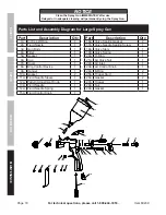
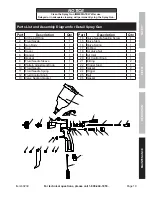
Item 60239
NOTICE
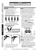
Clean the Spray Gun IMMEDIATELY after use.
Delayed or inadequate cleaning will permanently clog the Spray Gun.
SAFETY
Op
ERA
TION
M
AINTENANCE
SETU
p
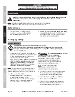
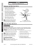
Initial Set Up
Read the ENTIRE IMpORTANT SAFETY INFORMATION section at the beginning of this
manual including all text under subheadings therein before set up or use of
this product.
Note:
For additional information regarding the parts listed in the following
pages, refer to the Assembly Diagram near the end of this manual.
Before Setup
1. This air tool may be shipped with a
protective plug covering the air inlet.
Remove this plug before set up.
2.
Before first use, clean the Spray Gun using
a solvent-based thinner.
If not removed,
the material used for testing and corrosion
prevention will contaminate paint.
Air Supply Setup
TO pREVENT SERIOUS INJURY FROM EXpLOSION:
Use only clean, dry, regulated, compressed air to power this tool. Do not use
oxygen, carbon dioxide, combustible gases, or any other bottled gas as a power
source for this tool.
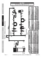
1. Incorporate a filter, regulator with pressure
gauge, in-line shutoff valve, and quick coupler
for best service, as shown on Figure A on
page 7 and Figure B on page 8.
An in-line shutoff ball valve is an important
safety device because it controls the air
supply even if the air hose is ruptured.
The shutoff valve should be a ball valve
because it can be closed quickly.
Note:
Do not use an automatic oiler system or
add oil to airline. The oil will contaminate the
material being propelled, ruining the final result.
2. Attach an air hose to the
compressor’s air outlet. Connect the
air hose to the air inlet of the tool.
Other components, such as a coupler plug
and quick coupler, will make operation
more efficient, but are not required.
WARNING! TO pREVENT SERIOUS INJURY
FROM ACCIDENTAL OpERATION:
Do not install a female quick coupler
on the tool.
Such a coupler contains
an air valve that will allow the air tool to
retain pressure and operate accidentally
after the air supply is disconnected.
Note:
Air flow, and therefore tool
performance, can be hindered by
undersized air supply components.
3. The air hose must be long enough to reach
the work area with enough extra length
to allow free movement while working.
4. Close the in-line shutoff valve between
the compressor and the tool.
5. Turn on the air compressor according to
the manufacturer’s directions and allow it
to build up pressure until it cycles off.
Summary of Contents for 60239
Page 1: ......


