


Page 8
For technical questions, please call 1-800-444-3353.
Item 60239
NOTICE
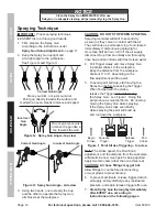
Clean the Spray Gun IMMEDIATELY after use.
Delayed or inadequate cleaning will permanently clog the Spray Gun.
SAFETY
Op
ERA
TION
M
AINTENANCE
SETU
p
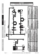
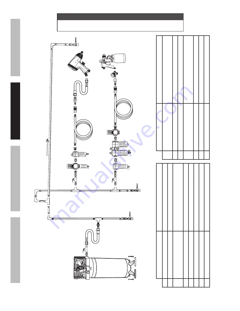
Figure
B:
Stationary
Air Supply Setup
N
L
L
O
M
C
C
Non-lubricated Tools
Lubricated Tools
H
I
I
J
J
K
H
F
G
E
Slope
F
F
B
B
A
A
C
D
Description
Function
A
Vibration Pads
For noise and vibration reduction
B
Anchor Bolts
Secures air compressor in place
C
Ball V
alve
Isolates sections of system for maintenance
D
Isolation Hose
For vibration reduction
E
Main
Air Line - 3/4″ min.
Distributes air to branch lines
F
Ball V
alve
To drain moisture from system
G
Branch
Air
Line
-1/2″
min.
Brings air to point of use
H
Air Hose
Connects air to tool
Description
Function
I
Filter
Prevents dirt and condensation contamination
J
Regulator
Adjusts air pressure to tool
K
Lubricator
*
For air tool lubrication
L
Coupler and Plug
Provides quick connection and release
M
Leader Hose
*
Increases coupler life
N
Air Cleaner / Dryer
*
Prevents moisture contamination
O
Air Adjusting
Valve
*
For fine tuning airflow at tool
*Optional components.
Summary of Contents for 60239
Page 1: ......


