background image

Page 4

For technical questions, please call 1-888-866-5797.

Items 68285 68284 


Sa
FE
ty

Op
E

ra
ti

O

n

Maint

E

nanc

E

S

E

tup

GrOunDinG inStructiOnS

1.  This appliance must be grounded. In the event 

of malfunction or breakdown, grounding provides 
a path of least resistance for electric current to 
reduce the risk of electric shock. This appliance 
is equipped with a cord having an equipment-
grounding conductor and a grounding plug. 
The plug must be plugged into an appropriate 
outlet that is properly installed and grounded in 
accordance with all local codes and ordinances.

2.  DANGER - Improper connection of the equipment-

grounding conductor can result in a risk of electric 
shock.  The conductor with insulation having an 
outer surface that is green with or without yellow 
stripes is the equipment-grounding conductor.  
If repair or replacement of the electric cord or 
plug is necessary, do not connect the equipment-
grounding conductor to a live terminal. Check with a 
qualified electrician or serviceman if the grounding 
instructions are not completely understood, or if 
in doubt as to whether the appliance is properly 
grounded. Do not modify the plug provided with 
the appliance – if it will not fit the outlet, have a 
proper outlet installed by a qualified electrician.

3.  This appliance is for use on a nominal 120 V 

circuit, and has a grounding plug that looks 
like the plug illustrated in Figure A.

Figure a:  3-prong plug

4.  A temporary adaptor, which looks like the 

adaptor illustrated in Figures B and C, may 
be used to connect this plug to a 2-pole 
receptacle as shown in Figure B if a properly 
grounded outlet is not available.

Figure B:  Grounding adapter

5.  The temporary adaptor should be used only 

until a properly grounded outlet can be installed 
by a qualified electrician. The green colored 
rigid ear, lug, and the like, extending from the 
adaptor must be connected to a permanent 
ground such as a properly grounded outlet 
box cover. Whenever the adaptor is used, it 
must be held in place by the metal screw.

Figure c:  Grounding adapter connection

6.  The adapter should not be used if a three-slot 

grounded receptacle is available.

7.  A qualified electrician should be consulted 

if there is any doubt as to whether an 
outlet box is properly grounded.

8.  A qualified electrician should be consulted 

if there is any doubt as to whether an 
outlet box is properly grounded.

Ground Fault circuit interrupter (GFci)

The appliance is equipped with a ground fault 
circuit interrupter (GFCI), which reduces the risk of 
electric shock.  Check that the receptacle is properly 
grounded and test the GFCI before each use.

1.  Plug the GFCI Power Plug into a 

grounded, 120 VAC electrical outlet.

2.  Press the TEST button. The GFCI 

indicator light should go out and power 
to the appliance should cut off.

WarninG! if the light does not go out when 
tESt button is pushed, do not use the 
appliance until it is properly repaired.

3.  To restore power after TEST, 

push the RESET button.

WarninG! if the appliance doesn’t start, 
stops while running, or if you experience 
an electric shock, disconnect the power cord 
and do not use the appliance. Have it repaired 
by a qualified electrician or replace it.

note:

 The Power Cord is not GFCI-protected from 

the GFCI to the 3-prong plug in the electrical outlet.

Summary of Contents for 68284

Page 1: ...se if product has no number Keep this manual and the receipt in a safe and dry place for future reference 20j When unpacking make sure that the product is intact and undamaged If any parts are missing or broken please call 1 888 866 5797 as soon as possible Copyright 2020 by Harbor Freight Tools All rights reserved No portion of this manual or any artwork contained herein may be reproduced in any ...

Page 2: ... the instructions before using the appliance 2 To reduce the risk of injury close supervision is necessary when an appliance is used near children 3 Do not contact moving parts 4 Only use attachments recommended or sold by the manufacturer 5 Do not use outdoors 6 To disconnect turn all controls to the off O position then remove plug from outlet 7 Do not unplug by pulling on cord To unplug grasp th...

Page 3: ...aner while you are tired or under the influence of drugs alcohol or medication A moment of inattention while operating may result in serious personal injury 26 Prevent unintentional starting Turn switch to the off position before plugging in 27 Have your Drain Cleaner serviced by a qualified repair person using only identical replacement parts This will ensure that the safety of the Drain Cleaner ...

Page 4: ...to a 2 pole receptacle as shown in Figure B if a properly grounded outlet is not available Figure B Grounding adapter 5 The temporary adaptor should be used only until a properly grounded outlet can be installed by a qualified electrician The green colored rigid ear lug and the like extending from the adaptor must be connected to a permanent ground such as a properly grounded outlet box cover When...

Page 5: ...le Not Included inStaLLatiOn inStructiOnS read the EntirE iMpOrtant SaFEty inFOrMatiOn section at the beginning of this manual including all text under subheadings therein before set up or use of this product note No assembly needed for Item 68285 assembly for 68284 tO prEVEnt SEriOuS inJury FrOM acciDEntaL OpEratiOn turn the rotation Switch of the tool to its position and unplug the tool from its...

Page 6: ... beginning of this manual including all text under subheadings therein before set up or use of this product user Operated controls Rotation Switch Cable Belt Guard Tool Holder item 61856 Belt Guard Knob Drum Foot Switch OFF FOr rEV Rotation Switch item 61857 Drum Cable Foot Switch Handle Belt Guard Knob Belt Guard Tool Holder Wheel Power Feed Lever Tension Knob Handle Locking Knob OFF FOr rEV ...

Page 7: ...ible retrieve a piece to inspect Once you can see the cause of the obstruction select the appropriate tool for the job Run the smallest available tool through the blockage to allow the backed up water to flow and carry away the debris as the drain is cleaned Once the drain is flowing more appropriate tools can be used on the rest of the blockage Keep in mind that the largest tool used should be no...

Page 8: ...ect the appliance for broken worn missing misaligned or binding parts or any other condition which may prevent safe and normal operation 6 Make sure that switches and handles move smoothly between positions and lock in place 7 Rotate the Drum and make sure that it turns freely without binding 8 Check that all warning labels are present firmly attached and readable 9 Make sure Belt Guard is securel...

Page 9: ...to be lifted use proper lifting techniques or seek assistance if needed Use caution when moving equipment up and down stairs Wear appropriate footwear to help prevent slipping on floor 12 To prevent Cable from whipping place Drain Cleaner within 2 feet of drain line or thread Cable through guide not included the greater the distance from the drain access the higher the risk of the cable twisting o...

Page 10: ...with one person controlling cable and another person controlling Foot Switch this can cause cable to kink twist or break which can also lead to serious personal injury 3 Make sure Rotation Switch is in FOr position 4 With the Drain Cleaner off pull the Cable out of Drum with both gloved hands and feed into the drain Gradually work the Cable as far into the drain as it will go 5 Step on the Foot Sw...

Page 11: ...e until all the tension is released 3 Place Rotation Switch in OFF position Freeing Lodged cutting tool 1 Release Foot Switch and turn the Rotation Switch to OFF position 2 Pull back on the Cable to free it from the blockage If the Cutting Tool will not come free place the Rotation Switch in rEV position WarninG Do not operate Drain cleaner in reverse for any longer than is needed to free the cutt...

Page 12: ... Feed Lever are within reach WarninG Only one person should operate the cable feed and the Foot Switch Do not operate the Drain cleaner with one person controlling the cable and another person controlling the Foot Switch this can cause the cable to kink twist and break which can also lead to serious personal injury 3 Loosen the Tension Knob then grab the Cable with both gloved hands and push the C...

Page 13: ...ng The Cable and tool will then need to be retrieved from drain and debris removed retrieving Drain cleaner cable 1 Once drain is clear turn on faucet or use a hose to flush debris out nOtE If water flow slows or stops resume using the Drain Cleaner to locate and clear blockage further down the drain 2 To retrieve cable set Power Feed Lever in reverse up position but make sure Rotation Switch is s...

Page 14: ...Drum WarninG tO prEVEnt SEriOuS inJury Do not attempt to remove a rotating cable cleaning Lubrication 1 The Drain Cleaner should be cleaned as needed with hot soapy water and or disinfectants WarninG risk of shock Do not allow water to get into the motor or any other electrical components 2 Dry Drain Cleaner before storing or using again 3 For Item 61857 Power Feed Drain Cleaner hose off the Power...

Page 15: ...let 3 3 Cable used is wrong size for drain pipe 4 4 Cable exposed to acid 5 5 Cable worn out 1 1 Do not force cable Let Cutting Tool do the work 2 2 Move Drain Cleaner to within 2 feet of drainpipe inlet 3 3 Change cable size 4 4 Clean and oil cable regularly 5 5 Replace cable Cable tangles in drum 1 Too much force on the cable 2 Motor running in reverse 3 Distributor tube frozen 1 Do not force ca...

Page 16: ...IDED THE PARTS LIST AND ASSEMBLY DIAGRAM IN THIS MANUAL AS A REFERENCE TOOL ONLY NEITHER THE MANUFACTURER OR DISTRIBUTOR MAKES ANY REPRESENTATION OR WARRANTY OF ANY KIND TO THE BUYER THAT HE OR SHE IS QUALIFIED TO MAKE ANY REPAIRS TO THE PRODUCT OR THAT HE OR SHE IS QUALIFIED TO REPLACE ANY PARTS OF THE PRODUCT IN FACT THE MANUFACTURER AND OR DISTRIBUTOR EXPRESSLY STATES THAT ALL REPAIRS AND PARTS...

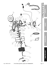
Page 17: ...Page 17 For technical questions please call 1 888 866 5797 Items 68285 68284 SaFEty OpEratiOn MaintEnancE SEtup 68285 assembly Diagram ...

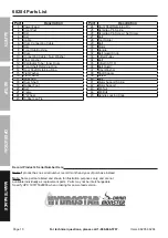
Page 18: ...iption 24 Drum Shaft Retaining Pin 25 Retaining Pin Spring 26 Retaining Pin Screw Set Screw 27 Bolt 28 Tool Holder 29 Bolt 30 Motor 31 Handle 32 Belt Guard Knob 33 V Belt Pulley 34 Bolt 35 V Belt A1118 36 Belt Guard 37 Fiber Washer 38 Shaft Spacer 39 Screw 40 Bolt 41 Motor Support Spring 42 Motor Support 43 M8 Nut 44 M8 Bolt 45 Handle Locking Knob 68284 parts List record product s Serial number He...

Page 19: ...Page 19 For technical questions please call 1 888 866 5797 Items 68285 68284 SaFEty OpEratiOn MaintEnancE SEtup 68284 assembly Diagram ...

Page 20: ...damages so the above limitation of exclusion may not apply to you THIS WARRANTY IS EXPRESSLY IN LIEU OF ALL OTHER WARRANTIES EXPRESS OR IMPLIED INCLUDING THE WARRANTIES OF MERCHANTABILITY AND FITNESS To take advantage of this warranty the product or part must be returned to us with transportation charges prepaid Proof of purchase date and an explanation of the complaint must accompany the merchand...

Reviews: