background image

Page 12

For technical questions, please call 1-800-444-3353.

Item 69039 


Roof Cover (18) Installation

Note:

 Door and Back Covers (19, 20) not shown on illustrations to provide a clear view of installation.

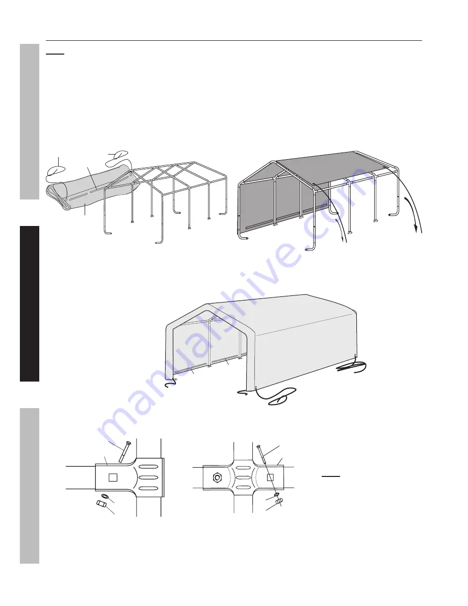
1.  Lay the Roof Cover (18) on the ground next to the frame. Make sure that the edges with black straps are 

alongside the Door/Back Covers (19,20) and one set of the fabric tubes is facing upwards, see Figure R.

2.  Tie each Rope (21) through an eyelet at the corner of the Roof Cover.

3.  Throw the other ends of the Ropes (21) over the frame.

4.  Move to the other side of the frame and pull the Cover over the frame.  Make sure that the Roof 

Cover is centred on the frame.  If small adjustment is needed, two people should pull together from 

the same end of the Portable Garage so that the Roof Cover does not become twisted.

21

18

21 fabric 

tube

Figure R:  Pull Roof Cover (18) Over Frame using Ropes (21)

5.  Insert the Bottom Rails into the fabric tubes on each side of the Roof Cover. 

Make sure the Bottom Rails are level and horizontal.

Figure S:  Insert Bottom Rails (4)

21

4

4

6.  Attach the Bottom Rails (4) to the Corner Studs (1-2) using 3-Way Rail Clamps (8), Bolts, Nuts and 

Washers (11, 12, 13), and to the Center Studs (1-1) with 4-Way Rail Clamps (7), as shown in Figure T.

Note:

 Only finger tighten 

the Nuts (12) at this point.

Figure T:  3 and 4-Way Rail Clamp (7, 8) Connections

11

8

13
12

11

13

7

12

7.  Make sure that all the bottom cross rails are of the same height from the ground, then tighten all Nuts (12).

8.  Secure the four corners to the Corner Legs (23) using Ratchet Tie-downs (22),  

see Securing Ratchet Tie-downs (22) on page 10.

SAFETY

MAINTENANCE

ASSEMBL

Y

Summary of Contents for 69039

Page 1: ... continuing improvements actual product may differ slightly from the product described herein Tools required for assembly and service may not be included When unpacking make sure that the product is intact and undamaged If any parts are missing or broken please call 1 800 444 3353 as soon as possible Save This Manual Keep this manual for the safety warnings and precautions assembly operating inspe...

Page 2: ...death Indicates a hazardous situation which if not avoided will result in death or serious injury Indicates a hazardous situation which if not avoided could result in death or serious injury Indicates a hazardous situation which if not avoided could result in minor or moderate injury Addresses practices not related to personal injury Double Insulated Canadian Standards Association Underwriters Lab...

Page 3: ...the area during assembly 7 Do not assemble when tired or when under the influence of drugs or medication 8 Product capabilities apply to properly and completely assembled product only Use Precautions 1 Do not use grill or any other type of fire under cover Cover may catch fire if exposed to heat rising from fire 2 Do not allow snow or debris to accumulate on this item 3 Heavy wet snow or strong wi...

Page 4: ... 4 For technical questions please call 1 800 444 3353 Item 69039 Specifications Overall Dimensions 10 W x 17 L x 9 3 H Center Height 9 3 Side Height 6 3 Pole Tubing Diameter 1 27 SAFETY MAINTENANCE ASSEMBLY ...

Page 5: ...all text under subheadings therein before set up or use of this product Note For additional information regarding the parts listed in the following pages refer to Parts List and Diagram on page 14 TO PREVENT SERIOUS INJURY Do not leave this product partially assembled Assemble this product completely at one time Figure A Frame Assembly Overview SAFETY MAINTENANCE ASSEMBLY ...

Page 6: ...parts in place to ensure a tight fit Figure B Roof Assembly Overview 1 Assemble ridge using three Rails 3 with 4 Way Ridge Connectors 6 1 between them and a 3 Way Ridge Connector 5 1 on each end The Rails connect to the straight ends of the Connectors and the curved free ends of the Connectors are angled down as shown Figure C Ridge Assembly 2 Connect a Rafter 2 to each free end of every Connector...

Page 7: ... by repeating the instructions in step 3 5 Connect the roof side rail assemblies to the ends of the Rafters 2 as shown below 6 2 2 2 2 2 5 2 6 2 5 3 3 6 2 5 2 6 2 5 3 3 3 3 Figure F Roof Side Rail Installation 6 Make sure all parts assembled up to this point are firmly joined together Tap parts together gently with a rubber mallet sold separately if needed Stud Foot and Leg Assembly 1 Assemble a F...

Page 8: ...h the Corner Legs 23 facing inward Figure H Stud Installation 3 After all four Studs 1 1 1 2 are in place rest that side of the assembly on the ground and raise the other side 4 Install four Studs 1 1 1 2 on the other side of the roof as explained in step 2 above Figure I Studs Installed on Both Sides 5 Make sure all parts assembled up to this point are firmly joined together Tap parts together ge...

Page 9: ...y are equal within a reasonable tolerance Note If measurements cannot be made correct then parts may not be seated together properly 10 2 A B 10 2 Figure J Verify and Adjust Frame Measurements 4 Once the frame is positioned leveled and squared anchor the four Corner Legs 23 as follows a Thread the Anchor 14 1 into the ground near the Corner Leg 23 until the top of the Anchor only extends about 3 a...

Page 10: ... in the Corner Leg 23 3 Lift and lower the Ratchet s handle to wind and tighten the strap onto the spindle CAUTION Excessive tightening will damage straps Covers and Corner Legs Figure L Threading Strap Through Spindle Figure M Inserting Hook into Corner Leg 23 Figure N Tightening Ratchet Releasing Ratchet Tie downs 22 1 Depress the spring loaded bar on the handle 2 Open ratchet handle completely ...

Page 11: ...Cover s 19 flaps wrap around the Rafters 2 and the Rope 21 is positioned inside the frame Reconnect the Rail 3 securely to the 3 Way Ridge Connector 5 1 Figure P Door Cover 19 Installation Place rope and flaps inside frame 5 1 5 1 5 2 5 3 3 3 3 3 zipper 3 3 3 19 3 Repeat step 2 for the 3 Way Side Connectors A B 5 2 5 3 so that the Door Cover 19 looks as shown in the illustrations above 22 Figure Q...

Page 12: ... together from the same end of the Portable Garage so that the Roof Cover does not become twisted 21 18 21 fabric tube Figure R Pull Roof Cover 18 Over Frame using Ropes 21 5 Insert the Bottom Rails into the fabric tubes on each side of the Roof Cover Make sure the Bottom Rails are level and horizontal Figure S Insert Bottom Rails 4 21 4 4 6 Attach the Bottom Rails 4 to the Corner Studs 1 2 using ...

Page 13: ...RAM IN THIS MANUAL AS A REFERENCE TOOL ONLY NEITHER THE MANUFACTURER OR DISTRIBUTOR MAKES ANY REPRESENTATION OR WARRANTY OF ANY KIND TO THE BUYER THAT HE OR SHE IS QUALIFIED TO MAKE ANY REPAIRS TO THE PRODUCT OR THAT HE OR SHE IS QUALIFIED TO REPLACE ANY PARTS OF THE PRODUCT IN FACT THE MANUFACTURER AND OR DISTRIBUTOR EXPRESSLY STATES THAT ALL REPAIRS AND PARTS REPLACEMENTS SHOULD BE UNDERTAKEN BY...

Page 14: ...Connector 2 5 2 3 Way Side Connector A 2 5 3 3 Way Side Connector B 2 6 1 4 Way Ridge Connector 2 6 2 4 Way Side Connector 4 7 4 Way Center Rail Clamp 8 8 3 Way End Rail Clamp 8 9 Foot 4 11 M6 45 Bolt 12 Part Description Illustration Qty 12 M6 Nut 12 13 M6 Washer 12 14 1 Anchor 4 14 2 Cable 1 30cm 4 14 3 Cable Clamp 4 15 Pin 4 16 Cotter Pin 4 18 Roof Cover 1 19 Door Cover 1 20 Back Cover 1 21 Rope...

Page 15: ...Page 15 For technical questions please call 1 800 444 3353 Item 69039 Assembly Diagram SAFETY MAINTENANCE ASSEMBLY ...

Page 16: ... the exclusion or limitation of incidental or consequential damages so the above limitation of exclusion may not apply to you THIS WARRANTY IS EXPRESSLY IN LIEU OF ALL OTHER WARRANTIES EXPRESS OR IMPLIED INCLUDING THE WARRANTIES OF MERCHANTABILITY AND FITNESS To take advantage of this warranty the product or part must be returned to us with transportation charges prepaid Proof of purchase date and...

Reviews: