background image

Page 5

For technical questions, please call 1-888-866-5797.

Item 58005 


SA

FE

TY

OP

ERA

TI

O

N

MAINT

ENANC

E

SE

TUP

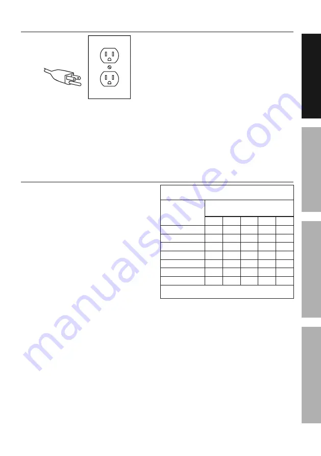
Grounded Tools: Tools with Three Prong Plugs


3-Prong Plug and Outlet

1.  Tools marked with “Grounding Required” have 

a three wire cord and three prong grounding 

plug.  The plug must be connected to a properly 

grounded outlet.  If the tool should electrically 

malfunction or break down, grounding provides 

a low resistance path to carry electricity 

away from the user, reducing the risk of 

electric shock.  

(See 3-Prong Plug and Outlet.)

2.  The grounding prong in the plug is connected 

through the green wire inside the cord to the 

grounding system in the tool.  The green wire 

in the cord must be the only wire connected to 

the tool’s grounding system and must never 

be attached to an electrically “live” terminal.  

(See 3-Prong Plug and Outlet.)

3.  The tool must be plugged into an appropriate outlet, 

properly installed and grounded in accordance 

with all codes and ordinances.  The plug and outlet 

should look like those in the preceding illustration.   

(See 3-Prong Plug and Outlet.)

Extension Cords

1. 

Grounded

 tools require a three 

wire extension cord.  

Double Insulated

 tools can 

use either a two or three wire extension cord.

2.  As the distance from the supply outlet increases, 

you must use a heavier gauge extension cord.  

Using extension cords with inadequately sized wire 

causes a serious drop in voltage, resulting in loss 

of power and possible tool damage.  

(See Table A.)

3.  The smaller the gauge number of the wire, the 

greater the capacity of the cord.  For example, 

a 14 gauge cord can carry a higher current 

than a 16 gauge cord.  

(See Table A.)

4.  When using more than one extension cord 

to make up the total length, make sure 

each cord contains at least the minimum 

wire size required.  

(See Table A.)

5.  If you are using one extension cord for more 

than one tool, add the nameplate


amperes 

and use the sum to determine the required 

minimum cord size.  

(See Table A.)

6.  If you are using an extension cord outdoors, make 

sure it is marked with the suffix “W-A” (“W” in 

Canada) to indicate it is acceptable for outdoor use.

7.  Make sure the extension cord is properly wired 

and in good electrical condition.  Always replace 

a damaged extension cord or have it repaired 

by a qualified electrician before using it.

8.  Protect the extension cords from sharp objects, 

excessive heat, and damp or wet areas.

TABLE A:  RECOMMENDED MINIMUM WIRE 

GAUGE FOR EXTENSION CORDS* (120/240 VOLT)

NAMEPLATE

AMPERES

(at full load)

EXTENSION CORD 

LENGTH

25´ 50´ 75´ 100´ 150´

0 – 2.0

18

18

18

18

16

2.1 – 3.4

18

18

18

16

14

3.5 – 5.0

18

18

16

14

12

5.1 – 7.0

18

16

14

12

12

7.1 – 12.0

18

14

12

10

-

12.1 – 16.0

14

12

10

-

-

16.1 – 20.0

12

10

-

-

-

* Based on limiting the line voltage drop to five volts at 

150% of the rated amperes.

Summary of Contents for Schneider 58005

Page 1: ...eference 21k When unpacking make sure that the product is intact and undamaged If any parts are missing or broken please call 1 888 866 5797 as soon as possible Copyright 2021 by Harbor Freight Tools All rights reserved No portion of this manual or any artwork contained herein may be reproduced in any shape or form without the express written consent of Harbor Freight Tools Diagrams within this ma...

Page 2: ...tion which if not avoided could result in minor or moderate injury Addresses practices not related to personal injury IMPORTANT SAFETY INFORMATION General Power Tool Safety Warnings Read all safety warnings and instructions Failure to follow the warnings and instructions may result in electric shock fire and or serious injury Save all warnings and instructions for future reference 7KH WHUP ƎSRZHU ...

Page 3: ... HQHUJL LQJ SRZHU WRROV WKDW have the Trigger on invites accidents 4 Do not overreach Keep proper footing and balance at all times This enables better control RI WKH SRZHU WRRO LQ XQH SHFWHG VLWXDWLRQV 5 Dress properly Do not wear loose clothing or jewelry Keep your hair clothing and gloves away from hot parts 6 Only use safety equipment that has been approved by an appropriate standards agency 8Q...

Page 4: ...entilation to keep fumes and gases from breathing zone and general area 6 Never lay the Soldering Iron down where the heated parts can contact flammable materials or electrical wires 7 This product is not a toy Keep it out of reach of children 8 Maintain labels and nameplates on the tool These carry important safety information If unreadable or missing contact Harbor Freight Tools for a replacemen...

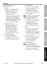
Page 5: ... must use a heavier gauge extension cord Using extension cords with inadequately sized wire causes a serious drop in voltage resulting in loss of power and possible tool damage See Table A 3 The smaller the gauge number of the wire the greater the capacity of the cord For example a 14 gauge cord can carry a higher current than a 16 gauge cord See Table A 4 When using more than one extension cord t...

Page 6: ...g Risk of Fire Do not cover ventilation ducts Keep flammable objects away WARNING marking concerning Risk of Electric Shock Properly connect power cord to appropriate outlet Specifications Electrical Rating 120VAC 60Hz 80W Temperature Range 302 F 896 F Tip Leakage Voltage 2mV Soldering Tips 900M Conical 0 2mm 0 5mm 900M Chisel 0 8mm Setup Before Use Components and Controls Soldering Tips Soldering...

Page 7: ...ll present a hazard while working 4 If wires are to be soldered thoroughly clean or scrape the wires so that only the clean metal is showing then make the wire splice 5 If other objects are to be soldered thoroughly clean or scrape the metal surfaces It may be necessary to apply acid flux not included to the metal surfaces before soldering Notice If soldering on printed circuit boards too much hea...

Page 8: ...seconds Buttons become non operational To unlock press and hold 1 2 and 3 Buttons for three seconds 4 Clean and tin Tip apply a sufficient amount of rosin core solder to melt over the entire Soldering Tip Wipe the Tip on the sponge until the Tip is clean and shiny 5 Apply solder to the wire splice or metal to be soldered not the Soldering Tip When the splice or metal is hot enough it will melt the...

Page 9: ...inished to store setting 4 Automatic Standby a Enter Settings mode then press b Press 1 Screen will display Stb and current status will be shown c Press to set Standby time 1 to 120 minutes or set to OFF d Press 1 when finished to store setting 5 Automatic Shutdown NOTE This feature will only work if Automatic Standby is on After entering Shutdown the Soldering Station cannot be controlled until p...

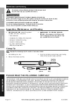
Page 10: ...f the supply cord of this power tool is damaged it must be replaced only by a qualified service technician Change Tip Note Replace the Soldering Tip if it cracks or becomes eroded 1 Let Soldering Iron cool 2 Remove Nut Sleeve and Tip 3 Push Tip into Sleeve place Sleeve over heating element then secure in place with Nut Heating Element Tip Sleeve Nut PLEASE READ THE FOLLOWING CAREFULLY THE MANUFACT...

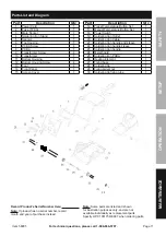
Page 11: ...Set 1 17 Manual Temperature Button Set 1 18 Power Switch 1 19 Soldering Iron Outlet 1 20 Soldering Iron Cable 1 21 Soldering Iron handle end sleeve 1 22 Soldering Iron handle sleeve 1 23 Soldering Iron handle 1 24 Metal board 1 25 Soldering iron PCBA 1 26 Heating Element 1 27 Fixing base 1 28 Soldering tip 1 29 Fixing swivel nut 1 30 Soldering tip fixing tube 1 30 22 Record Product s Serial Number...

Page 12: ...lusion or limitation of incidental or consequential damages so the above limitation of exclusion may not apply to you THIS WARRANTY IS EXPRESSLY IN LIEU OF ALL OTHER WARRANTIES EXPRESS OR IMPLIED INCLUDING THE WARRANTIES OF MERCHANTABILITY AND FITNESS To take advantage of this warranty the product or part must be returned to us with transportation charges prepaid Proof of purchase date and an expl...

Reviews: