For technical questions, please call 1-888-866-5797
7
CODE RETRIEVAL PROCEDURE
Using the Scan Tool
CODE RETRIEVAL PROCEDURE
6
Retrieving and using Diagnostic Trouble Codes (DTCs) for
troubleshooting vehicle operation is only one part of an
overall diagnostic strategy.
CODE RETRIEVAL PROCEDURE
Never
replace a part based only on the DTC definition.
Each DTC has a set of testing procedures, instructions and
flow charts that must be followed to confirm the location of
the problem. Always refer to the vehicle's service manual
for detailed testing instructions.
Check your vehicle thoroughly before performing
any test.
ALWAYS
observe safety precautions whenever working on a
vehicle.
1.
Turn the ignition off.
2.
Locate the vehicle's 16-pin Data Link
Connector (DLC).
Some DLCs have a plastic cover
that must be removed before
connecting the Scan Tool cable
connector.
If the Scan Tool is ON, turn it OFF
BEFORE connecting the Scan
Tool to the DLC.
3.
Connect the Scan Tool to the vehicle’s
DLC. The cable connector is keyed and
will only fit one way.
If you have problems connecting the cable connector to the DLC,
rotate the connector 180°.
If you still have problems, check the DLC on the vehicle and on
the Scan Tool.
4.
Turn the ignition on.
DO NOT
start the engine.
5.
When the Scan Tool is properly connected to the vehicle’s DLC, the
unit automatically turns ON.
If the unit does not power on automatically, it may indicate there
is no power present at the vehicle’s DLC connector. Check the
fuse panel and replace any burned-out fuses.
If replacing the fuse(s) does not correct the problem, consult your
vehicle’s repair manual to identify the proper computer (PCM)
fuse/circuit, and perform any necessary repairs before proceeding.
Using the Scan Tool
CODE RETRIEVAL PROCEDURE
7
6.
The Scan Tool automatically starts a check of the vehicle’s
computer to determine which type of communication protocol it is
using. When the Scan Tool identifies the computer’s communication
protocol, a communication link is established.
A PROTOCOL is a set of rules and procedures for regulating
data transmission between computers, and between testing
equipment and computers. As of this writing, five different types
of protocols (ISO 9141, Keyword 2000, J1850 PWM, J1850
VPW and CAN) are in use by vehicle manufacturers.
If the Scan Tool fails to link to the vehicle’s computer, a
“Communication Error” message shows.
- Ensure your vehicle is OBD2 compliant.
- Verify the connection at the DLC, and verify the ignition is ON.
- Turn the ignition OFF, wait 5 seconds, then back ON to reset
the computer.
- Press the
LINK
to continue.
If the Scan Tool
cannot
link to the vehicle’s computer after three
attempts, the message “Contact Technical Support” displays.
- Press
SYSTEM MENU
to return to the System Menu.
- Turn the ignition off, and
disconnect the Scan Tool.
- Contact Technical Support for
assistance.
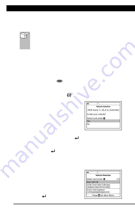
7.
If the Scan Tool can decode the Vehicle
Identification Number (VIN) for the
vehicle under test, the Confirm Vehicle
screen displays.
If the information shown is correct for the vehicle under test,
select
Yes
, then press
ENTER
. Proceed to step
10
.
If the information shown is not correct for the vehicle under test,
or if you wish to manually select the vehicle, select
No
, then
press
ENTER
. Proceed to step
8
.
If the Scan Tool
cannot
decode the Vehicle Identification
Number (VIN) for the vehicle under test, the Select Vehicle
screen displays. Proceed to step
8
.
8.
When
No
is selected from the Vehicle
information screen, the Select Vehicle
screen displays. The Select Vehicle
screen lists the three most recently
tested vehicles.
To select a previously tested vehicle,
select the desired vehicle, then press
ENTER
. Proceed to step
10
.


