


1 2
INSTALLATION INSTRUCTIONS CONT.
INSTALLING THE APPLIANCE
Follow the steps below to install your new Harbour
Cooktop.
WARNING!
DO NOT use a silicon sealant to seal the appliance
to the bench top.
This will make it difficult to remove the appliance
from the aperture in future, particularly if it needs to
be serviced.
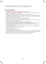
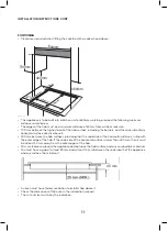
Note: The sealing strip (A) is already applied to your
cooktop.
1. Place the bracket (B) over the holes that match
the size of the screws. There are one set of screw
holes in each corner of the cooktop.
2. Slightly tighten a screw (C) through the bracket
(B) so that the bracket is attached to the hob, but
so that you can still adjust the position. Carefully
turn the hob back over and then gently lower it
into the aperture hole that you have cut out.
3. On the underneath of the hob, adjust the
brackets into a position that is suitable for
your worktop.
Then fully tighten the screws (C) to secure the hob
into position.
1 2
INSTALLATION INSTRUCTIONS CONT.
INSTALLING THE APPLIANCE
• Remove the pan supports, the burner lid and
flame spreader and carefully turn the appliance
upside down and place it on a cushioned mat.
Take care that the Ignition devices and flame
supervision devices are not damaged in this
operation.
• Apply the sponge provided around the edge of
the appliance.
• Do not leave a gap in the sealing agent or
overlap the thickness.
WARNING!
DO NOT use a silicon sealant to seal the appliance
to the bench top.
This will make it difficult to remove the appliance
from the aperture in future, particularly if it needs to
be serviced.
1. Place the bracket (B) over the holes that match
the size of the screws. There are one set of screw
holes in each corner of the cooktop.
2. Slightly tighten a screw (C) through the bracket
(B) so that the bracket is attached to the hob, but
so that you can still adjust the position. Carefully
turn the hob back over and then gently lower it
into the aperture hole that you have cut out.
3. On the underneath of the hob, adjust the
brackets into a position that is suitable for
your worktop.
Then fully tighten the screws (C) to secure the hob
into position.
Installing the appliance
Bottom view
of the screws.There are one set of screw holes in each
corner of the hob
(H)
.
Slightly tighten a screw
(C) through the bracket
(B) so
that the bracket is attached to the hob, but so that you
can still adjust the position .
.
2 Carefully turn the hob back over and then gently lower
it
into the aperture hole that you have cut out.
.
3 On the underneath of the hob, adjust the brackets into
a
position that is suitable for your worktop.
Then fully tighten the screws
(C) to secure the hob into
position.
(A) SEALING STRIP
(C) SCREW
(B) BRACKET
17
Remove the pan supports, the burner lid
and flame spreader and carefully turn the
appliance upside down and place it on a
cushioned mat.
Take care that the Ignition devices and
flame
supervision devices are not damaged
in this operation.
2. Apply the sponge provided around the
edge of
the appliance.
3.
1.
Do not leave a gap in the sealing agent or
overlap the thickness.
3ODFHWKHEUDFNHW
%RYHUWKHKROHVWKDWPDWFKWKHVL]H
7KLVZLOOPDNHLWGLI¿FXOWWRUHPRYHWKH
DSSOLDQFHIURPWKHDSHUWXUHLQIXWXUH
SDUWLFXODUO\LILWQHHGVWREHVHUYLFHG
Do not use a silicon sealant to seal the
appliance against the aperture.
Installing the appliance
Bottom view
of the screws.There are one set of screw holes in each
corner of the hob
(H)
.
Slightly tighten a screw
(C) through the bracket
(B) so
that the bracket is attached to the hob, but so that you
can still adjust the position .
.
2 Carefully turn the hob back over and then gently lower
it
into the aperture hole that you have cut out.
.
3 On the underneath of the hob, adjust the brackets into
a
position that is suitable for your worktop.
Then fully tighten the screws
(C) to secure the hob into
position.
(A) SEALING STRIP
(C) SCREW
(B) BRACKET
17
Remove the pan supports, the burner lid
and flame spreader and carefully turn the
appliance upside down and place it on a
cushioned mat.
Take care that the Ignition devices and
flame
supervision devices are not damaged
in this operation.
2. Apply the sponge provided around the
edge of
the appliance.
3.
1.
Do not leave a gap in the sealing agent or
overlap the thickness.
3ODFHWKHEUDFNHW
%RYHUWKHKROHVWKDWPDWFKWKHVL]H
7KLVZLOOPDNHLWGLI¿FXOWWRUHPRYHWKH
DSSOLDQFHIURPWKHDSHUWXUHLQIXWXUH
SDUWLFXODUO\LILWQHHGVWREHVHUYLFHG
Do not use a silicon sealant to seal the
appliance against the aperture.
1 2
INSTALLATION INSTRUCTIONS CONT.
INSTALLING THE APPLIANCE
• Remove the pan supports, the burner lid and
flame spreader and carefully turn the appliance
upside down and place it on a cushioned mat.
Take care that the Ignition devices and flame
supervision devices are not damaged in this
operation.
• Apply the sponge provided around the edge of
the appliance.
• Do not leave a gap in the sealing agent or
overlap the thickness.
WARNING!
DO NOT use a silicon sealant to seal the appliance
to the bench top.
This will make it difficult to remove the appliance
from the aperture in future, particularly if it needs to
be serviced.
1. Place the bracket (B) over the holes that match
the size of the screws. There are one set of screw
holes in each corner of the cooktop.
2. Slightly tighten a screw (C) through the bracket
(B) so that the bracket is attached to the hob, but
so that you can still adjust the position. Carefully
turn the hob back over and then gently lower it
into the aperture hole that you have cut out.
3. On the underneath of the hob, adjust the
brackets into a position that is suitable for
your worktop.
Then fully tighten the screws (C) to secure the hob
into position.
Installing the appliance
Bottom view
of the screws.There are one set of screw holes in each
corner of the hob
(H)
.
Slightly tighten a screw
(C) through the bracket
(B) so
that the bracket is attached to the hob, but so that you
can still adjust the position .
.
2 Carefully turn the hob back over and then gently lower
it
into the aperture hole that you have cut out.
.
3 On the underneath of the hob, adjust the brackets into
a
position that is suitable for your worktop.
Then fully tighten the screws
(C) to secure the hob into
position.
(A) SEALING STRIP
(C) SCREW
(B) BRACKET
17
Remove the pan supports, the burner lid
and flame spreader and carefully turn the
appliance upside down and place it on a
cushioned mat.
Take care that the Ignition devices and
flame
supervision devices are not damaged
in this operation.
2. Apply the sponge provided around the
edge of
the appliance.
3.
1.
Do not leave a gap in the sealing agent or
overlap the thickness.
3ODFHWKHEUDFNHW
%RYHUWKHKROHVWKDWPDWFKWKHVL]H
7KLVZLOOPDNHLWGLI¿FXOWWRUHPRYHWKH
DSSOLDQFHIURPWKHDSHUWXUHLQIXWXUH
SDUWLFXODUO\LILWQHHGVWREHVHUYLFHG
Do not use a silicon sealant to seal the
appliance against the aperture.
Installing the appliance
of the screws.There are one set of screw holes in each
corner of the hob
(H)
.
Slightly tighten a screw
(C) through the bracket
(B) so
that the bracket is attached to the hob, but so that you
can still adjust the position .
.
2 Carefully turn the hob back over and then gently lower
it
into the aperture hole that you have cut out.
.
3 On the underneath of the hob, adjust the brackets into
a
position that is suitable for your worktop.
Then fully tighten the screws
(C) to secure the hob into
position.
(A) SEALING STRIP
(C) SCREW
(B) BRACKET
17
Remove the pan supports, the burner lid
and flame spreader and carefully turn the
appliance upside down and place it on a
cushioned mat.
Take care that the Ignition devices and
flame
supervision devices are not damaged
in this operation.
2. Apply the sponge provided around the
edge of
the appliance.
3.
1.
Do not leave a gap in the sealing agent or
overlap the thickness.
3ODFHWKHEUDFNHW
%RYHUWKHKROHVWKDWPDWFKWKHVL]H
7KLVZLOOPDNHLWGLI¿FXOWWRUHPRYHWKH
DSSOLDQFHIURPWKHDSHUWXUHLQIXWXUH
SDUWLFXODUO\LILWQHHGVWREHVHUYLFHG
Do not use a silicon sealant to seal the
appliance against the aperture.


