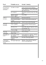
background image

3

Operator safety

Watch for this symbol 

. It means WARNING, CAUTION,

NOTE. Your safety is involved so be alert!
Note the following recommended precautions and safe operating
practices.

Read and understand this instruction book before using the

equipment. It is equally important that other operators of this
equipment read and understand this book.

Local law may demand that the operator be certified to use spray
equipment. Adhere to the law.

Pressure test with clean water prior to filling with chemicals.

Wear protective clothing.

Rinse and wash equipment after use and before servicing.

Depressurize equipment after use and before servicing.

Never service or repair the equipment whilst it is operating.

Disconnect electrical power before servicing.

Always replace all safety devices or shields immediately after

servicing.

If an arc welder is used on the equipment or anything connected

to the equipment, disconnect power leads before welding. Re-
move all inflammable or explosive material from the area.

Do not eat, drink or smoke whilst spraying or working with con-

taminated equipment.

Wash and change clothes after spraying.

Wash tools if they have become contaminated.

In case of poisoning, seek doctor or ambulance. Remember to

identify chemicals used.

Keep children away from the equipment.

Do not attempt to enter the tank.

If any portion of this instruction book remains unclear after read-

ing it, contact your HARDI dealer for further explanation before
using the equipment.

Summary of Contents for BL Series

Page 1: ...brication 10 Readjustment of the boom 12 Changing of valves and diaphragms 13 Nozzle tubes and fittings 14 Off season storage 14 Operational problems 16 Technical specifications 18 Pictorial symbols 20 Preassembly information 21 Assembly 22 Spare parts drawings 27 BL Instruction book 673224 GB 04 2002 HARDI INTERNATIONAL A S reserve the right to make changes in design or to add new features withou...

Page 2: ... the laws of the Member States on the safety of machines 89 392 EEC as amended by directives 91 368 EEC and 93 368 EEC with special reference to Annex 1 of the Directive on essential safety and health requirements in relation to the construction and manufacture of machines B was manufactured in conformity with the standards current at that time that implements a harmonised standard in accordance w...

Page 3: ...ng Never service or repair the equipment whilst it is operating Disconnect electrical power before servicing Always replace all safety devices or shields immediately after servicing If an arc welder is used on the equipment or anything connected to the equipment disconnect power leads before welding Re move all inflammable or explosive material from the area Do not eat drink or smoke whilst sprayi...

Page 4: ...ription The Hardi BL models consist of a pump frame with tank of 200 or 300 litre capacity with basket filter M 70 operating unit and 6 or 8 metre SB booms The design of the diaphragm pump is simple with easily accessible diaphragms and valves that ensures liquid does not come in contact with the vital parts of the pump The tank made of impact proof and chemical resistant polyethylene has a purpos...

Page 5: ...5 Operation diagram 1 Suction filter 2 Pump 3 On off and pressure regulation valve 4 Distribution valve 5 Sprayer boom 1 2 3 4 5 ...

Page 6: ...he tractor will have decreased braking efficiency 4 Be careful when filling lifting the sprayer the first time The pump is mounted directly to the tractor P T O 1 Undo the 2 allen screws on coupling and remove key 2 Slide pump onto P T O shaft 3 Replace key and tighten allen screws 4 Secure pump with supplied chains to prevent rotation Roadworthyness When driving on public roads and other areas wh...

Page 7: ... pattern See Spray Technique book Small adjustments of the boom height can usually be made with the 3 point suspension from the tractor raising or lowering the sprayer In crops where greater adjustments are needed the boom height can be changed manually by removing the 4 bolts holding the boom to the frame Note This is best done by 2 persons or with a mechanical hoist Pulsation damper The air pres...

Page 8: ...ng to the intended travelling speed Remember the number of revolutions on the P T O must be kept between 300 600 r min 4 Turn main on off handle 1 to spraying position B 5 Now turn the pressure regulating valve 3 to until the required pressure is indicated on the pressure gauge 6 Operating the control unit while driving To close the entire boom turn the handle 1 to position A This takes the pressu...

Page 9: ...oose the seal Maintenance In order to derive full benefit from the sprayer for many years the following few but important rules should be kept Cleaning the Sprayer see Spray Technique book Filters Clean filters ensure Sprayer components such as valves diaphragms and operating unit are not hindered or damaged during operation Nozzle blockages do not occur whilst spraying Long life of pump A blocked...

Page 10: ...se ball bearing grease lithium grease No 2 NOTE If the sprayers are cleaned with a high pressure cleaner or it has been used to spray fertilizer we recommend lubrication of the entire machine Page to find more information Oil Grease Operation hours Position on sprayer 2 ...

Page 11: ...11 1 X 40 2 X 20 3 X 40 4 X 40 11 6 10 10 8m SB T213 0010 T201 0002 ...

Page 12: ...ound If it is over tight it will not function If it is too loose it will yawn forward and back movement under spraying Lubricate coupling before adjusting spring tension Slacken screw nut A to decrease breakaway resistance Do not overtighten better to loose than over tight Again minor adjustments in the field may be necessary Ensure also channel bolts B are tight Outersection 8m SB The hindge shou...

Page 13: ...ced correctly It is recommended to use new gaskets 3 when changing or checking the valves Diaphragms Remove the diaphragm cover 4 after having dismantled the valve compartment as indicated above The diaphragm 5 may then be changed If fluids have reached the crankcase re grease the pump thoroughly Check also the drain hole at the bottom of the pump is not blocked ...

Page 14: ... For radial connections only hand tighten them The O ring must be lubricated ALL THE WAY ROUND before refitting For face connections a little mechanical leverage may be used Off season storage When the spraying season is over you should devote some extra time to the sprayer before it is stored Hoses Check that none of the hoses are caught or have sharp bends A leaky hose can give an annoying delay...

Page 15: ...essure regulation valve is completely loosened The spring is thereby relieved and operation difficulties are avoided at starting up next season Anti freeze precaution If the sprayer is not stored in a frost proof place you should take the following precautions Put at least 5 litres of 33 anti freeze mixture in the tank and let the pump run a few minutes so that the entire system including spray ho...

Page 16: ...ower pressure at the nozzles Foreign bodies stuck in the pump valves with the result that these cannot close tightly against the valve seat This reduces pump efficiency Poorly reassembled pumps especially diaphragm covers will allow the pump to suck air resulting in reduced or no capacity Therefore ALWAYS check 1 Suction and nozzle filters are clean 2 Hoses for leaks and cracks paying particular a...

Page 17: ... all filters Check tightness gaskets O rings of all fittings on suction side Use foam damping additive Replace See section Changing valves and diaphragms No spray from blower when turned on Lack of pressure Pressure dropping Pressure increasing Formation of foam Liquid leaks from bottom of pump Air leak on suction Air in system Suction nozzle filters clogged Incorrect assembly Pump valves blocked ...

Page 18: ...300 20 595 520 210 588 22 26 Tank Spraying Pump Measure Weight size width model a x b x c l m cm kg 6 500 100 190 160 93 200 6 600 100 190 160 99 8 600 100 190 200 105 6 500 100 190 160 99 300 6 600 100 190 160 105 8 600 100 190 200 114 c b a Technical specifications Measure and weights ...

Page 19: ...0 29 23 0 45 28 0 52 30 0 59 34 0 67 10 17 0 45 22 0 59 28 0 82 30 0 89 33 0 97 15 16 21 27 30 33 Rotation per min r min Capacity l min Suction height 0 0 m Power consumption kW Max pressure 15bar Weight 15 6 kg r min 300 400 500 540 600 bar l min kW l min kW l min kW l min kW l min kW 0 13 0 15 16 0 15 19 0 22 20 0 29 21 0 29 5 10 0 22 12 0 29 15 0 37 16 0 45 18 0 52 10 9 0 29 12 0 45 14 0 52 15 ...

Page 20: ...20 Pictorial symbols Description Function Connection Warning Operating Service adjustment Liquid flow Pressure Cleaning Lubrication Winter storage Operational problems Technical specifications ...

Page 21: ... is easiest done before assembly To verify connection of hoses a function diagram is included on the last page Packaging information Materials used for packaging are environmentally compatible They can be safely deposited or they can be burnt in an incinerator Recycling Cardboard Can recycle up to 99 and therefore should be put into the waste collection system Polystyrene foam Can be recycled Fluo...

Page 22: ...e O rings where indicated Lubricate them before assembly Where O rings are not indicated use sealing tape 3 Operating unit and distribution valve are assem bled and bolted to rack Screw pressure gauge on to operating unit Do not overtighten See back of gauge Remember to pierce casing after installation ...

Page 23: ...ore fitting A Suction hose to pump B From pump C Return to tank F Feed hoses to boom NOTE For sake of good order it may be necessary to shorten some hoses for example suction hose A This is best done when assembly is com pleted and before hoses are secured with plastic straps ...

Page 24: ...t boom wings Be cautious when folding boom for the first time See section on boom breakaway in instruc tion book 10 Nozzle tubes are supplied with one lock nozzle saddle per tube A The rest can slide lengthwise B allowing for extension and contraction A B 6 7 9 8 T145 0010 ...

Page 25: ...ed hoses REMEMBER Lubricate O rings before fitting 11 Fit tubes using synthetic nut Press down 1 turn 2 Do not overtighten 12 Mount filter and COLOR TIPS 13 For 8 metre SB fit boom transport lock Arrow indi cates forward direction of travel T145 0011 T145 0011 T145 0012 ...

Page 26: ...26 14 Check hose connections are in accordance with diagram 15 Organise hoses it may be necessary to shorten some of them Secure with straps F B A C ...

Page 27: ...27 500 4 9 95 A1 ...

Page 28: ...28 600 4 9 95 A5 ...

Page 29: ...29 B5 15 5 79 ...

Page 30: ...30 B6 18 2 91 ...

Page 31: ...31 Dampers HJ73 30 9 93 B300 ...

Page 32: ...32 SB 6 8 10m 18 2 91 D2 ...

Page 33: ...33 ...

Page 34: ...34 BL 200 300 18 2 91 E2 ...

Page 35: ...35 Notes ...

Page 36: ...36 Notes ...

Reviews: