background image

6 - Maintenance

6.12

1. Connect the sprayer to the tractor.

2. Fold out the boom.

3. Support the boom wing by e.g. some brackets in min. two places,
to prevent boom tilt during adjustment.

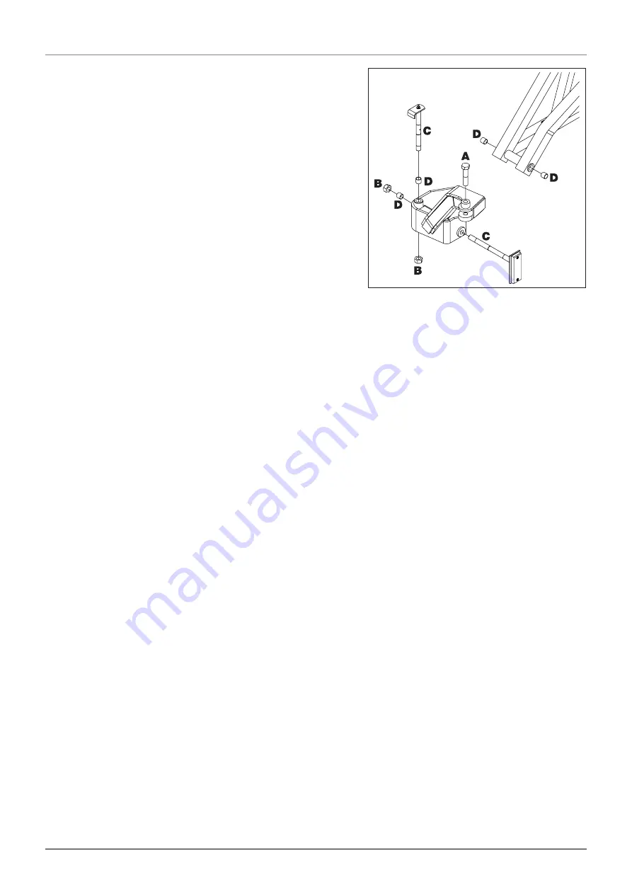
4. Loosen and remove bolt (A) from the eye bolt on the cylinder.

5. Loosen and remove the nuts (B), and remove the pins (C).

6. Replace all bearings (D).

7. Reassemble in reverse order.

8. Perform same procedure at the other boom wing.

1000 hours service - Change of bearings between centre and
inner section

Summary of Contents for COMMANDER Classic DELTA

Page 1: ...COMMANDER Classic DELTA www hardi international com 67002600 Version 1 02 GB 12 2005 Instruction book ...

Page 2: ...omplete and correct As this instruction book covers more models and features or equipment which are available in certain countri es only please pay attention to paragraphs dealing with precisely your model Published and printed by HARDI INTERNATIONAL A S We congratulate you for choosing a HARDI plant protection product The reliabi lity and efficiency of this product depend upon your care The first...

Page 3: ...ump 5 Valves and symbols 5 Valves and symbols 5 Green valves Green disc Pressure valve 6 Black valves Black disc Suction valve 6 Agitation valve 6 Electrical operated MANIFOLD valves optional equipment 7 Self cleaning filter 7 HARDI FILLER 8 Control unit 8 EVC control unit 8 Boom 9 Boom and terminology 9 Equipment 10 Driving technique for STEER and SELF TRACK 10 STEER TRACK optional 10 SELF TRACK ...

Page 4: ...ical connections 9 Power supply 9 Control boxes 9 Installation of control unit brackets 9 Installation of control box EVC control unit 9 Road safety kit 10 Pendulum lock setup on LPY model 10 Liquid system 11 Self cleaning filter Choice of restrictor 11 Track gauge axles and wheels 12 Altering the track gauge 12 Transport 13 General info 13 Transport lock 13 Transport brackets 14 Boom 15 Pendulum ...

Page 5: ...of rinsing tank optional equipment 6 Filling of clean water tank optional equipment 6 Adjustment of EVC operating unit 7 Safety precautions crop protection chemicals 7 Filling chemicals through tank lid 8 Filling Liquid chemicals by HARDI FILLER 8 Filling Powder chemicals by HARDI FILLER 9 Operating the control unit while spraying 10 Quick reference 11 Cleaning 12 General info 12 Cleaning the tank...

Page 6: ...ice Air brake filters optional equipment 8 250 hours service Hydraulic brakes 9 250 hours service Expansion bottle SELF TRACK only 9 1000 hours service Transmission shaft 9 1000 hours service Wheel bearings and brakes 10 1000 hours service Change of bearings between centre and inner section 12 Occasional maintenance 13 General info 13 Pump valves and diaphragms renewal 13 Cone check renewal for EV...

Page 7: ... system Z model 3 Hydraulic system Y model 4 TRACKER damping system 5 Mechanical problems 6 Emergency operation Liquid system 6 8 Technical specifications Dimensions 1 Overall dimensions 1 Wheel and axle dimensions 1 Conversion factors SI to Imperial units 2 Specifications 3 Pump model 363 10 0 3 Pump model 463 5 5 3 Pump model 463 10 0 3 Pump model 463 6 5 3 Pump model 463 12 0 3 Filters and nozz...

Page 8: ...Table of contents TOC 6 ...

Page 9: ...ive on essential health and safety requirements in relation to the construction and manufacture of machines B was manufactured in conformity with the provisions in other relevant COUNCIL DIRECTIVES C was manufactured in conformity with the current standards implementing harmonised standards in accordance with Article 5 2 and other relevant standards declare that the following product Importer HARD...

Page 10: ...1 CE Declaration 1 2 ...

Page 11: ... and change clothes after spraying Wash tools if they have become contaminated In case of poisoning immediately seek medical advice Remember to identify chemicals used Keep children away from the equipment If any portion of this instruction book remains unclear after reading it contact your HARDI dealer for further expla nation before using the equipment Be carefull not to hit people or surroundin...

Page 12: ...laced in the transport brackets If an arc welder is used on the equipment or anything connected to the equipment disconnect power leads befo re welding Remove all inflammable or explosive material from the area Never dismount the hose if the machine is in operation Disconnect the cleaner and the water supply before the high pressure hose is dismounted The External Cleaning Device should not be use...

Page 13: ...ion An identification plate fitted on the frame indicates producer name model own weight max height max pressure of the hydraulic system if fitted and max pressure of the spray liquid system A B C Identification plates The COMMANDER Classic is divided into three zones A Clean zone a Working zone and an Application zone referring to the level of pos sible pesticide contamination In the following th...

Page 14: ...Frame boom centre frame and other main steel components have identification plates indicating type and part number not illustra ted REFERENCE NO is the main reference number of the complete machine When driving on public roads and other areas where the highway code applies or areas where there are special rules and regulations for marking and lights on implements you should observe these and equip...

Page 15: ...mpact frame which also has a strong chemical and weather resistant electrostatic lacquer coat Screws nuts etc have been DELTA MAGNI treated to be resistant to corrosion The main tank made of impact proof UV resistant and chemical resistant polyethylene has a purposeful design with no sharp corners for easy cleaning Nominal contents 2200 2800 3200 or 4200 l A large easy to read tank contents indica...

Page 16: ...the addition of optional extras on both pressure SmartValve B and suction SmartValve C and a third valve A for agitation and for rinsing nozzle optional equipment Furthermore the suction manifold can be fitted with a return valve which ensures better draining of the sprayer before cle aning A quick reference D can be fitted to manifold plate for a quick overview of the functions General info MANIF...

Page 17: ...e located on the discs for easy identification and operation A function is activated opened by turning the handle towards the desired function The valves at the MANIFOLD are distinguished by coloured identification on the function labels Symbols corresponding to every possible function of use are located on the discs for easy identification and operation A function is activated by turning the hand...

Page 18: ...e valve is marked with an arrow on the green disc that indicates the amount of liquid that passes through the valve If handle is turned to a position near the tip of the arrow then only a small amount of liquid is allowed to pass the valve Otherwise if handle is turned to a position in the wide end of the arrow it means that a larger amount is passing the valve This gives the posibility to contino...

Page 19: ...be operated manually if the power to the valve motor is disconnected With the self cleaning filter the impurities that exist in the spray liq uid will by pass the filter and be recirculated back to the tank via the return flow Function diagram 1 From pump 2 Double filter screen 3 Guide cone 4 To operating unit 5 Exchangeable restrictor 6 Return to tank 7 Screw joint 8 Ball valve Ball valve 8 shoul...

Page 20: ...cal Valve Control The ON OFF is linked to the section valves which results in a very quick response to ON OFF The operating unit is constructed of modules and is electrically controlled via a remote control box The unit is fit with build in HARDI MATIC EVC control unit The HARDI FILLER is situated in the working zone on the sprayers left side just behind the MANIFOLD valves When being used it shou...

Page 21: ...ended and fully hydraulically operated all functions are controlled via the Direct Hydraulic System D H The boom is also equipped with individual boom tilt control and a hydraulic pendulum lock Individual folding of outer sections enable alternative boom widths Outer sections incorporate spring loaded breakaway The boom is available in 18 20 21 24 27 and 28 m working width All booms are 2 folded F...

Page 22: ...turning on hillsides To avoid overbalancing pay attention to these guidelines 1 Avoid sudden tight turns 2 Slow down before entering a curve or turning and drive with a constant low speed during the turn 3 Never slow down too fast never brake heavily and never stop suddenly in a curve or when turning on a hillside B when the sprayer is articulated 4 Be careful when turning on uneven ground 5 Set t...

Page 23: ...unted suction filter and the self cleaning filter which is situated on the backside of the MANIFOLD system The remote pressure gauge is integrated in the platform This gauge measures the working pressure in the boom tubes as close to the nozzles as possible The outputs stated in the nozzle charts are always based on the pressure measured at the nozzle Always adjust pressure when cali brating and s...

Page 24: ...fitted on the trailer wheels by means of a sup porting frame which is bolted to a mounting on the wheel axle Mudguards are available for all wheel configurations Before driving remove the stop wedges and place them in the stor age brackets Mudguards optional equipment ...

Page 25: ...nt should be carried out every time the protection film is washed off Support leg For the unloading of the sprayer you need a crane When unloading with a crane please observe the lifting points as shown on the pictu re and make sure that the straps or belts used for lifting are strong enough The support leg is stored in the bracket on the sprayer s right side when the sprayer is attached to the tr...

Page 26: ...place sprayer at level and firm ground to avoid sprayer falling down from the jack When the sprayer needs wheel mounting wheel changing brake or wheel bearing changing etc then jack up the sprayer under the axle as shown Jack up the sprayer ...

Page 27: ...ction guard 4 Do not touch or stand on the transmission shaft when it is rotating safety distance 1 5 meter 5 Prevent protection guards from rotating by attaching the chains allowing sufficient slack for turns 6 Make sure that protection guards around tractor P T O and implement shaft are intact 7 Always STOP ENGINE and remove the ignition key before carrying out maintenance or repairs to the tran...

Page 28: ...and assemble male and female parts again 6 Fit the shaft to tractor P T O and sprayer pump shaft ATTENTION Female part marked with a tractor towards trac tor First installation of the transmission shaft is done in the following way 1 Attach sprayer to tractor and set sprayer height in the position with shortest distance between the tractor and sprayer pump P T O shafts 2 Stop engine and remove ign...

Page 29: ...ft etc all hoses cables and wires are held by the hose bracket fitted to the sprayer platform Check that the length of the hoses and cables are sufficient by tight turns SELF TRACK for COMMANDER 2200 2800 is connected as follows 1 Attach the tractor lower links in the two mountings of the SELF TRACK Adjust the length of the drawbar if necessary to obtain the best tracking choose the setting where ...

Page 30: ...the drawbar in a centred position in case of hydraulic leakage during transport on public roads The transport lock turnbuckle is fixed by linch pins If necessary the transport lock can be adju sted by turning the turnbuckle ATTENTION If possible lock the tractor hydraulic lever when the lift arms are in the correct position to avoid the sprayer weight resting on the stabiliser chains DANGER Do not...

Page 31: ...Connection requirements are A single outlet to raise or lower the boom A double outlet to fold or unfold the boom A double outlet for Hydraulic Slanting Control optional equipment The hydraulic hoses are marked with arrows to indicate direction of oil flow The hydraulic system requires an oil flow bet ween 10 and 90 l min 19 8 Imp gal min and a min pressure of 130 bar 1886 p s i The system has a b...

Page 32: ...ing then screw in the valve Certain tractor models are able to use Load Sensing without con necting an external sensing line But if optimal sensing control pres sure cannot be obtained an external sensing line needs to be mounted 3 Please consult your tractor dealer for correct setup and correct connection Before operating the hydraulics the valve should be adjusted accor ding to the specific trac...

Page 33: ...racket A has a hole spacing of 100 and 120 mm Check tractor instructions manual for information regar ding attachment points Three tubes B are supplied One two or all 3 may be used They can be bent and shortened A spacer C is also supplied to allow further attachment possibilities Find the best solution for your tractor or vehicle Tube B plate is staggered so if correctly orientated all boxes will...

Page 34: ...th position lamps must be folded out fitted in certain coun tries only Pendulum lock setup on LPY model When having a LPY model of the sprayer there is no hydraulic con trol unit as tractors hydraulic levers are used So to control the pen dulum lock then one switch on the spray control unit is used Place the pendulum lock label on the control unit box This label are pla ced on the sign originally ...

Page 35: ... the hose and the hose is mounted again If the required working pressure cannot be obtained the restrictor is too large Choose a smaller restrictor Start with a black one then a white and finally a red one When cleaning the filter remove hose N and the hose at the safety valve and check there are no residues Standard filter size is 80 mesh Filters of 50 and 100 mesh are availa ble and can be chang...

Page 36: ...rking brake 3 Place stop wedges in front of and behind RH wheel Jack up LH wheel support and secure sprayer body 4 Loosen bolts A for LH wheel axle 5 Loosen the pointed screw B on the brake operating arm 6 Extend or retract the axle A sack barrow and a rod will facilitate the operation 7 Tighten the clamp bolts A to a torque of 250 Nm 8 Tighten the pointed screw B again 9 Repeat the procedure on R...

Page 37: ...ly with the transport lock A combination of adjustments described in the follo wing part form each transport position This includes adjustment of the tranport lock and the wire mounting To change position of the wire 1 Loosen the nut and remove the bolt which holds the wire A to the mounting B 2 Place the wire A in correct position please refer to chart and reassemble When the boom is unfolded Ins...

Page 38: ...hoosing a position every adjustment must match the settings shown in chart Failure to do so may cause serious damage to the sprayer The transport bracket can be set at three different positions A B or C The setting must be identical on both sides To change transport bracket position 1 Lift and unfold the boom inner sections 2 Loosen and remove the bolts on each side of the platform which secures t...

Page 39: ...ed downwards Counterclockwise rotation The spring arrangement becomes shor ter and the steering arms are moved upwards Use a level to inspect the alignment to make sure the 4 steering arms are level When correct position is obtained 1 Refit the spring arrangement and tighten the big nut at the upper end of arrangement 2 Extra check that the spring arrangement is correctly refitted and then release...

Page 40: ...llows the movements of the trailer to a high extent Use position 3 when spraying very hilly land Pendulum effect adjustment When driving on slopes the boom can be slanted in order to match the local topography At delivery the boom is locked in pos 2 neutral which is used when driving on horizontal grounds The slanting angle is adjusted as follows and with the boom unfol ded 1 Remove the linch pin ...

Page 41: ...Adjustment of each steering arm is performed as follows 1 Loosen nuts A 2 Place a suitable tool e g a screwdriver in the hole B in the turn buckle and use the tool to rotate the turn buckle Clockwise rotation The turnbuckle becomes shorter and the distan ce between centre section and lift trailer decreases Counterclockwise rotation The turnbuckle becomes longer and the distance between centre sect...

Page 42: ...ay from the pawl To disengage the parking brake 1 Set pawl control clip in pos 1 2 Pull the lever a little forward to release the pawl from the ratchet and then push the lever fully backwards To engage the parking brake 1 Set pawl control clip in pos 2 2 Pull the lever firmly forwards until parking brake is fully engaged Emergency brake 1 Set pawl clip in pos 2 2 Attach the rope from the hole in t...

Page 43: ...t Red Supply line RH Yellow Control line LH Relieve parking brake before driving This system requires a tractor with compressor and air brake system with out let s for trailer brakes If the air hose s are disconnected with air in the brake air tank con trol pressure will be dumped and the brakes will engage fully If the sprayer must be moved with air in the tank and without the air hose s connecte...

Page 44: ...4 Sprayer setup 4 20 ...

Page 45: ...se the folding unfolding functions in areas with overhead power lines Unintended boom movements can cause contact with overhead power lines The boom unfolding folding can be done according to instructions below 1 Lift up the boom lift until the boom is clear of the transport brackets using the single acting hydraulic outlet lever 2 Unfold the boom completely using the double acting hydraulic outle...

Page 46: ...sides 9 Optional function 10 Optional function 11 Manual track control left right optional 12 Track control auto manual auto lock optional 13 Boom outer folding right For unfolding of the boom then do the following Check that pendulum 2 is locked 1 Push switch 4 upwards to lift the boom clear of the transport brackets 2 Push switch 8 downwards to unfold the inner sections Rear transport hooks dise...

Page 47: ...ng and filling hose is connected If this valve is opened without pump running liquid will stream out of the MANIFOLD Tank should normally be filled 1 3 with water before adding chemi cals Always follow instructions given on the chemical container Water is filled into the tank by removing the tank lid located at front of sprayer tank which is accessible from platform It is recommended to use as cle...

Page 48: ...ction Manifold towards Filling Device 4 The tank is now filled with water Keep an eye on the liquid level indicator 5 Turn handle on Suction Manifold away from Filling Device to discontinue filling process Then disengage pump 6 Disconnect suction tube B and replace cover The Fast Filling Device is operated as follows 1 Ensure spray liquid tank contains at least 50 litres of water 2 Remove cover A ...

Page 49: ...legislation regarding use of filling device In some areas it is prohibited to fill from open water reservoirs lakes rivers etc It is recommended only to fill from closed reservoirs mobile water tanks etc to avoid contamination Grip positions The Filling Device and the Fast Filling Device can be used simultane ously this gives even bigger filling capacity Grip positions used Quick coupler for exter...

Page 50: ...the pump The rinsing tank is situated under the main tank Only fill this tank with clean water The rinsing tank is filled through the inlet situated beneath the Suction Manifold valves Water can be filled directly through the inlet or through a socket piece optional equipment connected to a water hose A water level indicator limpid hose with floating ball is situated beneath the platform Rinsing t...

Page 51: ...emicals Before spraying the EVC operating unit is adjusted using clean water without chemicals 1 Choose the correct nozzle for the spray job by turning the TRIPLET nozzle bodies Make sure that all nozzles are the same type and capacity See the Spray Technique book 2 On off switch is activated against green 3 All distribution valve switches are activated against green 4 Pressure regulation switch i...

Page 52: ...OLD valves to correct position Black suction valve towards Suction from main tank green valve towards Agitation 3 Engage the pump and set P T O revolutions to 540 r p m 4 Add the chemicals through the main tank hole 5 When the spray liquid is well mixed turn handle on the green pressure valve towards Spraying position Keep P T O engaged so the spray liquid is continuously agitated until it has bee...

Page 53: ...e handle at the suction Manifold towards Main tank Turn agitation valve towards Agitation and turn pressure Manifold towards HARDI FILLER Close remaining valves 3 Check that bottom valve A at the FILLER is closed 4 Engage the pump and set P T O speed at 540 r min or 1000 r min depending on pump model 5 Open FILLER lid 6 Measure the correct quantity of chemical and fill it into the hop per 7 Open t...

Page 54: ...dle at the Suction Manifold towards Main tank and agitation valve towards Agitation Turn the green handle at the Pressure Manifold towards HARDI FILLER Close remaining valves 3 Engage the pump and increase P T O speed to 540 r min or 1000 r min depending on pump model 4 Open the bottom valve A at the FILLER Open FILLER lid 5 Engage the hopper rinsing device by opening valve C 6 Measure the correct...

Page 55: ...he agitation valve to Agitation if necessary The Quick reference are to be read like the signs designates the grip positions on the SmartValves for every use situa tions A designates water filling into the main tank B designates filling chemicals by using HARDI FILLER C designates spraying in the field Cleaning procedure D and should be repeated 3 times by using 1 3 of rinsing tank content each ti...

Page 56: ...a soakaway This is an area of ground that is not used for cropping You must avoid seepage or runoff of residue into streams water courses ditches wells springs etc The washings from the cleaning area must not enter sewers Drainage must lead to an approved soakaway 4 Cleaning starts with the calibration as a well calibrated sprayer will ensure the minimal amount of remaining spray liq uid 5 It is g...

Page 57: ...of the tank with clean water Note that some chemicals require the tank to be completely filled Add appropriate detergent and or deactivating agent e g washing soda or Triple ammonia 7 Start the pump and operate all controls enabling the liquid to come in contact with all the components Leave the dis tribution valves until last Some detergents and deactivating agents work best if left in the tank f...

Page 58: ... It is advisable to increase the forward speed double if possible and reduce the pressure to 1 5 bar 20 psi when spraying diluted remaining liquid in the field just sprayed Grip positions used ATTENTION If a cleaning procedure is given on the chemical label follow it closely Use of rinsing tank and rinsing nozzles optional equipment ATTENTION If the sprayer is cleaned with a high pressure cleaner ...

Page 59: ...eeze the Chemical Container Cleaning handle to clean this device Open HARDI FILLER lid again and assure that the hopper is empty When empty then close the HARDI FILLER bottom valve again 5 Turn the suction SmartValve towards Main tank and pressure SmartValve towards Spraying and spray liquid in the field you have just sprayed Cleaning of Main tank 6 Turn the suction SmartValve towards Rinsing tank...

Page 60: ...lin kage and armature separately be rinsed It is to be made certain however that the liquid in the lines in unchanged con centration is sprayed out so there should be an untreated patch available The drain valve is located and operated from the platform just besi de the main tank lid Pull the string to open the drain valve The valve is spring loaded but can be kept open by pulling the string upwar...

Page 61: ...on tact with oil products for longer periods Always follow the shown direction concerning recommended quan tity If no recommended quantity is given feed lubricator till new grease becomes visible Pictograms in lubrication oiling plans tell the following 1 Lubricant to be used see Recommended lubricants 2 Operating hours before next lubrication SLIDE BEARINGS Lithium grease with Molybdenumdisulphid...

Page 62: ...6 Maintenance 6 2 Trailer lubrication oiling plan ...

Page 63: ...6 Maintenance 6 3 With suspension Without suspension B 250 B 250 B 250 B 250 ...

Page 64: ...the suction hose B and steel clip A 1 Unscrew nut A and open filter 2 Check filter gauze B clean if necessary 3 Lubricate O ring C 4 Assemble filter again If the boom is equipped with In Line Filters unscrew the filter bowl to inspect and clean the filter When reassembling the O ring should be greased Alternative filter meshes are available See section on Technical spe cifications Filters and nozz...

Page 65: ...nsmission shaft Check and clean Drain the air tank for condensed water at the drain valve Check that these 9 bolts on each side of the COMMANDER are tight Retighten if necessary Bolt 8 and 9 are situated behind the spring Tightening torque Bolt 1 24 Nm retain nut on the backside of the mounting by a spanner while adjusting bolt 1 Bolt 2 9 280 Nm 10 hours service Retighten bolts suspension only 10 ...

Page 66: ...kes released 3 Apply the brake up to full pressure 4 Check for leaks with brakes applied Check the tyre pressure according to the table in Technical specifications 50 hours service Expansion bottle SELF TRACK only Tighten wheel bolts and nuts as follows with following torque wrench settings Wheel hub to rim plate 490 Nm 362 lbft Tightening sequence See illustration and tighten in order of num beri...

Page 67: ...eel 2 Rock the RH wheel to discover possible play in the bearings 3 If any play support the wheel axle to prevent the trailer from fal ling down from the jack 4 Remove hub cap A and cotter pin B Turn the wheel and tighten the castellated nut C until a slight resistance in the wheel rotation is felt 5 Loosen the castellated nut until the first notch horizontal or ver tical is aligned with the cotte...

Page 68: ... under the filter housing and pull out the retainer clip A The filter cartridge assembly will be pushed out by the springs inside the filter housing 3 Clean the filter cartridge Use water and an appropriate detergent or compressed air 4 Dry the parts and reinstall in the order shown The O ring should be lightly lubricated with silicone grease before installation 250 hours service Air brake filters...

Page 69: ...ithout air bubbles come out 3 Tighten brake hose before relieving the brake again Change the protection tube nylon bearings as described under Shield renewal on transmission shaft 1000 hours service Transmission shaft Check the oil level 1 Depressurize the expansion bottle through valve A first 2 Remove the level plug B and check that the oil level is reaching the level hole Add if the level is lo...

Page 70: ...eel hub and brake drum assembly Use a wheel pul ler if necessary 6 Vacuum clean the brake drum D for brake dust or rinse with water 7 Rinse the remaining parts on the brake carrier plate with water and dry them 8 Remove roller bearings E clean all parts in degreasing detergent and dry them 9 Check the brake drum diameter and lining thickness renew if worn Max wear rates on brake components Max dru...

Page 71: ... new sealing ring 16 Fill the hub and bearings with fresh grease before fitting it to the shaft 17 Fit the castellated nut Rotate the hub and tighten the castellated nut until a slight rotation resistance is felt 18 Loosen the castellated nut again until the first notch is aligned with the cotter pin hole in the shaft 19 Fit a new cotter pin and bend it 20 Fill the hub cap with fresh grease and ca...

Page 72: ...places to prevent boom tilt during adjustment 4 Loosen and remove bolt A from the eye bolt on the cylinder 5 Loosen and remove the nuts B and remove the pins C 6 Replace all bearings D 7 Reassemble in reverse order 8 Perform same procedure at the other boom wing 1000 hours service Change of bearings between centre and inner section ...

Page 73: ...e therefore impossible to specify Diaphragms Remove the diaphragm cover 4 The diaphragm 5 may then be changed If fluids have reached the crankcase re grease the pump thoroughly Also check that the drain hole at the bottom of the pump is not blocked Reassemble with the following torque setting Reassemble pump model 363 463 with the following torque setting Diaphragm cover 90 Nm 66 6 lbft Diaphragm ...

Page 74: ... B for the return line When the housing is drained there should be no liq uid flow through the return line If there is any leakage the valve cone E must be changed Remove the clip C and lift the motor housing off the valve housing Then unscrew the screw D and replace the valve cone E Reassemble in reverse order The level indicator reading should be checked regularly When the tank is empty the floa...

Page 75: ...ce seal D and assemble again 5 Assemble the valve assembly again using a new valve seat E Lubricate O rings F before assembly 6 Fit clip A again If the cord on the level indicator has to be changed the float guide pole is removed 1 Remove the tank drain valve see paragraph Drain valve seal renewal and loosen the fitting holding the pole in posi tion 2 Pull the pole down through the drain valve hol...

Page 76: ...ctor 3 Place tractor and sprayer on level ground horizontal 4 Unfold boom 5 Set slanting angle to neutral position horizontal Adjustment of hydraulic cylinders are done without pressure in the system Horizontal alignment of centre and inner section The MANIFOLD valve can be adjusted if it is too tight to operate or if it is too loose liquid leakage Correct setting is when the valve can be operated...

Page 77: ...he wire by the bolt A again Ad 1 1 Loosen the nuts A 2 Screw the bolts B a bit inwards to create some space between the boltheads and the profile C Proceed with adjustment of the locking device Ad 2 Ad 2 3 Loosen the two nuts D and E 4 Fold the boom section a little backwards 5 Rotate the turn buckle F to align the boom section Clockwise rotation The boom will point forwards backwards Counterclock...

Page 78: ...re screwed outwards the boom will point downwards If the nuts are screwed inwards the boom will point upwards The breakaway device is adjusted by increasing or decreasing the amount of spring loading Adjust the position of nut A on the eye bolt which holds the spring B The amount of spring loading needed can be observed when dri ving with the sprayer If the breakaway sections swing too much forwar...

Page 79: ...sen and remove jag nut D and counter nut C 9 Unscrew the yaw damper from the shaft and replace it with a new one Grease the top of the new damper 10 Place the jag nut D on the shaft again and fasten it against the new rubber damper Also fit counter nut C on the shaft again 11 Reassemble in reverse order Remember to position the nut C against the profile now 12 Carry out the same procedure at the o...

Page 80: ...newed B In a tight position If not they must be tightened Renewal of rubber dampers 1 Unfold the boom 2 Loosen and remove the bolt A and remove the cylinder to make room enough for next step 3 Loosen and remove the bolt B 4 Remove the rubber dampers C and replace them with new ones 5 Reassemble in reverse order Subsequently the yaw dampers must be equally tightened The rubber dampers are tightened...

Page 81: ...isconnected simultaneously 7 Grease all grease nipples 8 Remove the lifting gear again If too much play is found in the drawbar the wear bushes must be renewed 1 Place stop wedges in front of and behind both wheels 2 Jack up the frame and support it properly 3 If not a SELF TRACK model Remove the drawbar extension to reduce the weight of the drawbar 4 Loosen the two bolts A and support the bracket...

Page 82: ...it in reverse order Before fitting the needle bearing cups again check that needles is placed correctly Avoid dust and dirt in the new bearings 6 Repeat procedure to the opposite part of the transmission shaft Replacement of transmission shaft cross journals 1 Remove bolt A lock B and grease nipple C Twist uni CV joint cover 1 4 turn and pull it backwards 2 Remove the synthetic bearings and protec...

Page 83: ...yre to 100 130 kPa 14 5 19 p s i then check whether both beds are seated perfectly on the rim If any of the beads do not seat correctly deflate the assembly and re centre the beads before starting inflation of the tyre If the beads are seated correctly on the rim at 100 130 kPa inflate the tyre to a maximum of 250 kPa 36 p s i until they seat perfectly on the rim 10 Never exceed the maximum mounti...

Page 84: ...e relief valves in the TRACKER s damping system is factory set to open at 40 bar 580 p s i which is adequate for most conditions If the damping seems too soft or too hard the settings can be adjusted Connect manometers to the Minimesh couplings and control if pressure is equal for both sides A Adjusting screw B Self locking nut TRACKER damping pressure setting SELF TRACK only ...

Page 85: ...e glycerine filled pressure gauges and store them frost free in vertical position 9 Apply a thin layer of anti corrosion oil e g SHELL ENSIS FLUID CASTROL RUSTILLO or similar on all metal parts Avoid oil on rubber parts hoses and tyres 10 Fold the boom in transport position and relieve pressure from all hydraulic functions 11 All electric plugs and sockets are to be stored in a dry plastic bag to ...

Page 86: ...Maintenance 6 26 Spare parts To see updated spare part information the website www agroparts com can be visited Here all parts information can be accessed when free registration has been made Spare parts ...

Page 87: ...tightly against the valve seat This reduces pump efficiency 5 Poorly reassembled pumps especially diaphragm covers will allow the pump to suck air resulting in reduced or no capacity 6 Hydraulic components that are contaminated with dirt result in rapid wear to the hydraulic system Therefore ALWAYS check 1 Suction pressure and nozzle filters are clean 2 Hoses for leaks and cracks paying particular...

Page 88: ... spray from boom when turned on Lack of pressure Pressure dropping Pressure increasing Formation of foam Liquid leaks from bottom of pump Operating unit not functioning FAULT Air in system Pump valves blocked or worn Nozzles worn Excessive liquid agitation Wrong polarity Fill suction hose with water for initial prime Check for obstructions and wear Check flow rate and replace nozzles if it exceeds...

Page 89: ...g at PCB in junction box Boom lift raises to max pos when trac tor hydraulics are engaged Oil heats up in Closed Centre systems Individual ram does not move FAULT Insufficient oil supply Clogged restrictors a or b in by pass block Back pressure in return line exceeds 20 bar Internal leaks in flow regulator Oil flow must be min 10 l min and max 90 l min Check tractor hydraulic oil level Remove and ...

Page 90: ...t rear of sprayer Dirt in the restrictor port of the cylinder Check for correct solenoid electric hydraulic hook up Check for short circuit in wiring in the junction box at rear of sprayer Boom slow eradic Ram not functioning Hydraulic system fold tilt functions will not operate One function fold or tilt will not ope rate Multiple hydraulic functions with one switch activated Regulation valve inco...

Page 91: ...rcuit Ad ballast on front of tractor TRACKER damping system Sprayer trails unstable Rear hydraulic rams are too tight and vehicle continues straight ahead when trying to turn FAULT Hydraulic circuit leaking Pressure relief valve set too high Repair leak prime Adjust pressure relief valves Pressure relief valve s set too low Adjust pressure relief valves ...

Page 92: ...nctions of the operating unit manually First disconnect the multi plug from the control box Now manually turn the emergency control knobs The problem may be due to a blown fuse A fuse is placed inside the box Fuse type Thermo Emergency operation Liquid system Mechanical problems ...

Page 93: ...000 1540 to 2000 1540 to 2000 1730 to 2000 1730 to 2000 1780 to 2000 with mudguards N A 1680 to 2250 1820 to 2250 1820 to 2250 1820 to 2250 1820 to 2250 1820 to 2250 alternative shortening axles N A 1590 to 2000 1590 to 2000 1590 to 2000 1780 to 2000 1780 to 2000 1780 to 2000 coil spring suspended axle N A 1820 to 2250 1820 to 2250 1820 to 2250 2020 to 2250 2020 to 2250 2060 to 2250 with mudguards...

Page 94: ... mile x 0 621 Velocity km h mile h x 0 621 km h m s x 0 277 Quantities Area l ha gal acre x 0 089 Volume ml fl oz x 0 0352 l Imp pt x 0 568 l gal x 0 22 Pressure bar lb inv p s i x 14 504 Temperature C F C x 1 8 32 Power kW hp x 1 341 Torque Nm lb ft x 0 74 All units used in this manual are SI units In some occasions Imperial units are used Use following factors to convert SI units to Imperial uni...

Page 95: ...8 Technical specifications 8 3 Pump model 463 12 0 Pump model 463 6 5 Pump model 463 10 0 Pump model 463 5 5 Pump model 363 10 0 Specifications ...

Page 96: ... 4200 sprayers 4 0 mm 0 15748 in HYDRAULIC BRAKES Max hydraulic pressure 150 bar 2176 p s i AIR BRAKES single line Air pressure relieved brakes 5 3 5 6 bar Air pressure drop to activate 0 8 1 3 bar AIR BRAKES dual line Load apportioning valve pressure settings Relieved 0 bar Empty 1 6 bar 23 2 p s i Half 3 4 bar 49 3 p s i Full Air tank pressure 230 95 R44 3 6 52 134 145 230 95 R48 3 6 52 136 147 ...

Page 97: ...g tyres always use tyres with min load index as specified DANGER Never inflate tyres more than to the pressure specified in the table Over inflated tyres can explode and cause severe personal injuries See the part Occasional maintenance Change of tyre ...

Page 98: ...leaned The tank hose and synthetic fittings can be incinerated at an authorised disposal plant The metallic parts can be scrapped Always follow local legislation regarding disposal Materials used Tank HDPE Hoses PVC Valves mainly glass filled PA Fittings PA Disposal of the sprayer Materials and recycling ...

Page 99: ...e that maximum current for every connector is 2 Amp Total current for the whole connector box may not exceed 10 Amp EVC 1 LH direction indicator Yellow 2 Free Blue 3 Frame White 4 RH direction indicator Green 5 RH rear position lamp Brown 6 Stop lamps Red 7 LH rear position lamp Black The wiring is in accordance with ISO 1724 Rear lights Electrical connections ...

Page 100: ...5 Brn Blu Sec 4 Brn Blu Sec 3 Brn Blu Sec 2 Brn Blu Sec 1 Brn Blu Gnd L R Foam marker No 4 Not used 2 6 5 1 3 Opt 1 Pressure sensor Brn Blu Opt 2 RPM sensor or anemometer Brn Blu Blk Speed Brn Blu Blk Flow Brn Blu Blk L end nozzle Pendulum lock at HAY LPY Brn Blu R endnozzle Pendulum lock at HAY LPY Brn Blu Reg Yellow Brn Blu Bypass EC on off Brn Blu Sec 9 User defined A B 2 x x Sec 8 User defined...

Page 101: ...6 17 2 Tilt right up 3 Tilt right down 4 Tilt left up 5 Tilt left down 6 A flow reverse 7 B flow forward 8 Fold right 9 Fold right 10 Fold left 11 Fold left 12 Fold inner 13 Fold inner 14 Slant 15 Slant 16 Pendulum lock 17 Fold 18 Slant Plug positions for LPZ hydraulics ...

Page 102: ...8 Technical specifications 8 10 Boom hydraulic Z Boom Hydraulic LPY 05 Boom hydraulic Y Electrical chart EVC Charts ...

Reviews: