


3 - Description
3.9
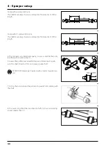
Filling chemicals without
Vortex assistance
Start Vortex
Adjustable Agitation
External Cleaning Device
(optional equipment)
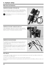
The ChemFiller is situated in the working zone on the sprayers left
side, just behind the MANIFOLD valves. When being used it should
be folded down by grabbing the handle, then unlock it by pushing
the grib just below the handles left side and pulling it against your-
self.
When retracting the ChemFiller after use, then unlock it by pushing
the grib just below the handles left side and push it back in storing
position until a click is heard. Then ChemFiller is locked into the stor-
age position.
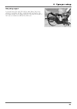
When folded down in use position a grip for chemical container cle-
aning and a valve for ChemFiller Vortex nozzle are visible on the
backside of the ChemFiller.
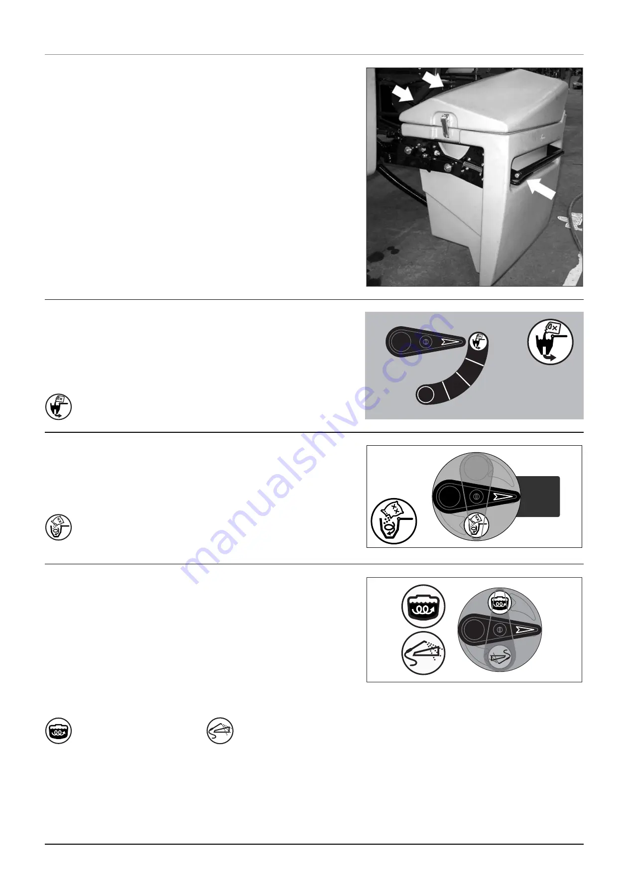
The valve is used simultaneously with the ChemFiller. Open valve
when chemicals is going to be filled into the ChemFiller. Note that
suction SmartValve must be positioned at “Suction from Main tank” to
make the valve work.
This valve activates the Vortex flushing of the ChemFiller. The valve is
situated behind the ChemFiller and is only visible when ChemFiller is
folded down in use position.
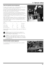
With the adjustable Agitation valve it is possible to combine spraying
with a high volume rate at high pressure with agitation at same time.
This is controlled continously on the valve: The valve is marked with an
arrow on the disc that indicates the amount of liquid that passes
through the valve. If the handle is turned to a position near the tip of
the arrow, then only a small amount of liquid is allowed to pass the
valve resulting to a lesser extent of agitation. Otherwise if the handle is
turned to a position in the wide end of the arrow then a large amount
of liquid will pass the valve resulting to a large extent of agitation.
Agitation valve
ChemFiller Vortex nozzle - Yellow label
ChemFiller suction valve - Red labels (optional equipment)
ChemFiller
Summary of Contents for COMMANDER TWIN FORCE 3200
Page 8: ...Table of contents TOC 6 ...
Page 10: ...1 CE Declaration 1 2 ...
Page 14: ...2 Safety notes 2 4 ...
Page 66: ...6 Maintenance 6 2 Boom lubrication oiling plan 32 36 m ...
Page 67: ...6 Maintenance 6 3 Trailer lubrication oiling plan ...
Page 107: ...8 Technical specifications 8 11 Charts Boom hydraulic Y Boom hydraulic Z ...
Page 108: ...8 Technical specifications 8 12 Sprayer hydraulic Fan transmission ...
Page 109: ...8 Technical specifications 8 13 Electrical specifications for boom and work light ...
Page 110: ...8 Technical specifications 8 14 ...


