4 - Sprayer setup
4.14
ATTENTION! Depending on configuration of the machine the
track gauge can be altered in the range from 1500 mm to
2000 mm, or from 1800 mm to 2250 mm.
ATTENTION! When wheels has been mounted or re-tightened,
the plastic nut covers must be placed on the nuts afterwards.
ATTENTION! The wider the track width is, the better is the sta-
bility of the sprayer. HARDI recommends to work with widest
possible track width.
WARNING! Place the jack under the axle and lift the wheel to
remove load from the clamps before tightening the clamp
bolts to the specified torque.
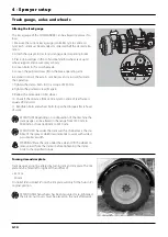
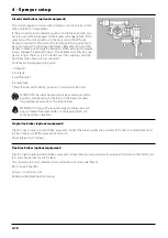
The track gauge of the COMMANDER can be altered stepless as fol-
lows,
1. Measure the current track gauge (centre RH tyre to centre LH
tyre). Each side must be extended or retracted half the desired alte-
ration.
2. Attach the sprayer to tractor and engage tractor parking brake.
3. Place stop wedges in front of and behind RH wheel. Jack up LH
wheel, support and secure sprayer body.
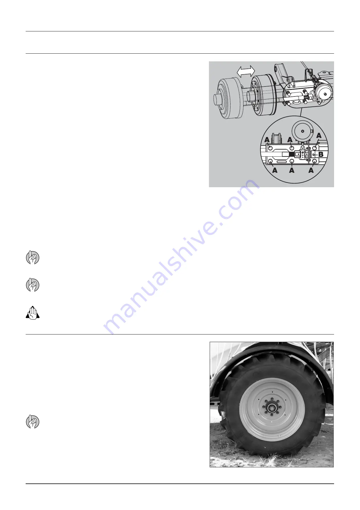
4. Loosen bolts (A) for LH wheel axle.
5. Loosen the pointed screw (B) on the brake operating arm.
6. Extend or retract the axle. A sack barrow and a rod will facilitate
the operation.
7. Tighten the clamp bolts (A) to a torque of 250 Nm.
8. Tighten the pointed screw (B) again.
9. Repeat the procedure on RH wheel.
10. Check if the distance from centre tyre to centre of rear frame is
equal at RH and LH.
11. Retighten bolts and wheel bolts to specified torque after 8 hours
of work.
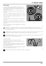
Track gauge can not be altered by turning rim and rim plate. The rim
plate can be fitted left or right. With an offset of :
+ 61 mm
- 50 mm
On 18.4x38” and 20.8x38” rims the rim plate will only fit the hub in it’s
original position.
Turning rim and rim plate
Altering the track gauge
Track gauge, axles and wheels
Summary of Contents for COMMANDER TWIN FORCE 3200
Page 8: ...Table of contents TOC 6 ...
Page 10: ...1 CE Declaration 1 2 ...
Page 14: ...2 Safety notes 2 4 ...
Page 66: ...6 Maintenance 6 2 Boom lubrication oiling plan 32 36 m ...
Page 67: ...6 Maintenance 6 3 Trailer lubrication oiling plan ...
Page 107: ...8 Technical specifications 8 11 Charts Boom hydraulic Y Boom hydraulic Z ...
Page 108: ...8 Technical specifications 8 12 Sprayer hydraulic Fan transmission ...
Page 109: ...8 Technical specifications 8 13 Electrical specifications for boom and work light ...
Page 110: ...8 Technical specifications 8 14 ...


