


6 - Maintenance
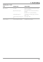
6.14
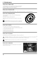
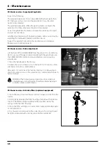
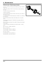
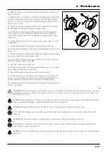
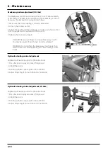
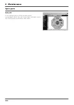
If it becomes difficult to build up sufficient pressure or if pressure
fluctuations occur, it may be necessary to renew cone and cylinder.
A spare parts kit can be ordered - contact your local dealer to service
the unit.
1. Remove 4 x screws (A) and remove the housing.
2. Remove 4 x screws (B) and remove cone.
3. Loosen nut (C) in bottom of the cone.
4. Replace with parts from spare parts kit.
5. Reassemble in reverse order.
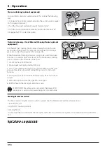
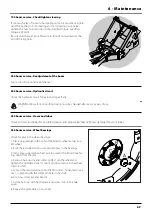
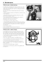
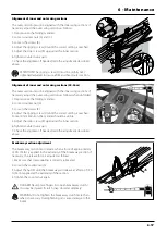
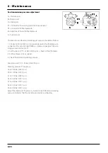
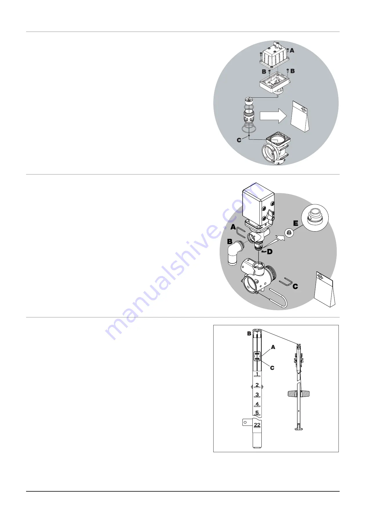
Periodically check the distribution valves for proper sealing. Do this
by running the sprayer with clean water and open all distribution
valves. Cautiously remove the clip (A) and pull out the hose (B) for
the return line. When the housing is drained, there should be no liq-
uid flow through the return line. If there is any leakage, the valve
cone (E) must be changed. Remove the clip (C) and lift the motor
housing off the valve housing. Then unscrew the screw (D) and
replace the valve cone (E). Reassemble in reverse order.
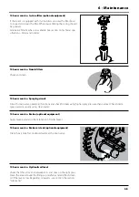
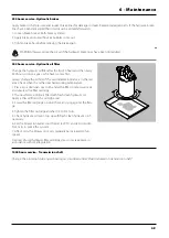
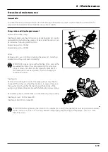
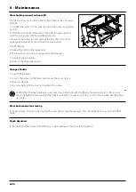
The level indicator reading should be checked regularly. When the
tank is empty, the float should lie on the stop pin, of the rod, and
the O-ring on the indicator should be positioned at the top position
line (A).
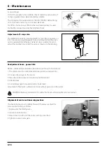
If any deviation is found, pull out the plug (B), loosen screws (C), and
adjust the length of the cord.
Level indicator adjustment
Cone check/renewal for EFC distribution valve
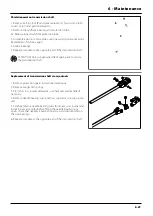
Cone check/renewal for EFC operating unit
Summary of Contents for COMMANDER TWIN FORCE 3200
Page 8: ...Table of contents TOC 6 ...
Page 10: ...1 CE Declaration 1 2 ...
Page 14: ...2 Safety notes 2 4 ...
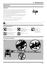
Page 66: ...6 Maintenance 6 2 Boom lubrication oiling plan 32 36 m ...
Page 67: ...6 Maintenance 6 3 Trailer lubrication oiling plan ...
Page 107: ...8 Technical specifications 8 11 Charts Boom hydraulic Y Boom hydraulic Z ...
Page 108: ...8 Technical specifications 8 12 Sprayer hydraulic Fan transmission ...
Page 109: ...8 Technical specifications 8 13 Electrical specifications for boom and work light ...
Page 110: ...8 Technical specifications 8 14 ...


