background image

2 - Safety notes

8

Never service or repair the equipment while it is operating. Always replace all safety devices or shields immediately 
after servicing.

Disconnect electrical power before servicing and depressurize equipment after use and before servicing.

If an arc welder is used on the equipment or anything connected to the equipment, disconnect power leads before 
welding. Remove all inflammable or explosive material from the area.

The External Cleaning Device should not be used if essential parts of the equipment have been damaged, including 
safety devices, high pressure hoses, etc.

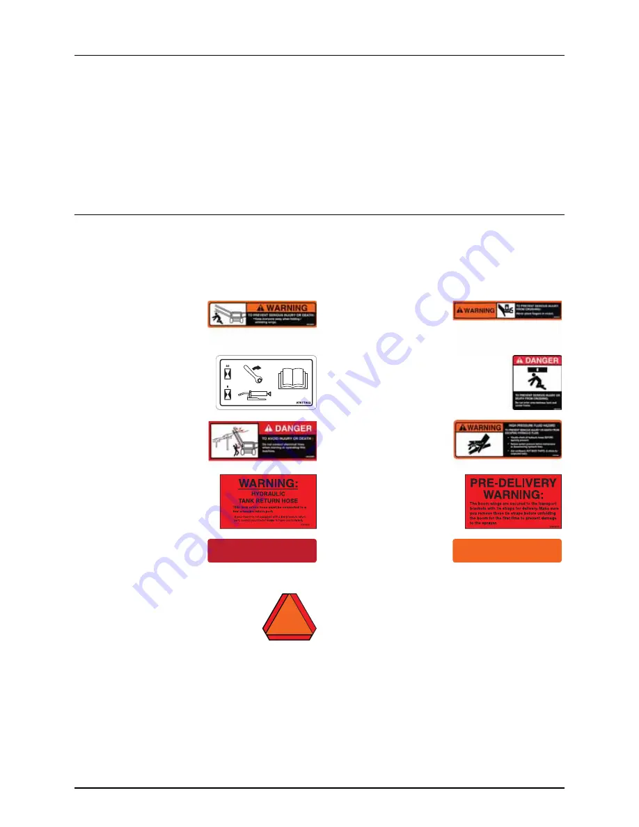
Label explanation

The labels designate potential dangerous places on the machine. Anybody working with or being in close range of the 
sprayer must respect these labels!

The labels should always be clean and readable! Worn or damaged labels must be replaced with new ones. Contact your 
local dealer for new labels.

10532803 - Fold wings

Keep away when folding, 
unfolding wings.

10532703 - Crush fingers

Never place fingers in clutch.

97617903 - Breakaway

See Boom Operator’s manual 
for maintenance.

10616103 - Paralift

Risk of serious injury or death from crushing. 
Do not enter between tank and center frame.

10533003 - Overhead lines

Do not contact electrical lines 
when moving or operating!

10532503 - Hydraulic hazard

Risk of serious injury or death 
from escaping hydraulic fluid.

97610103 - Tank return hose

Tank return hose must be 
connected to a low pressure 
port.

97606603 - Pre-Delivery

Remove tie straps before 
unfolding boom first time.

10533803 - Red Reflector

10533903 - Amber Reflector

10601403 - SMV Sign

Slow moving vehicle

Summary of Contents for Delta Force Boom

Page 1: ...The Sprayer Operator s Manual DELTA FORCE BOOM Instruction book 67025103 Version 1 00 US 05 2017 ...

Page 2: ......

Page 3: ...67025103 Version 1 00 US 05 2017 HARDI reserves the right to make changes in design material or specification without notice thereof HARDI and other product names are registered trademarks of HARDI Inc in the U S and in other countries ...

Page 4: ......

Page 5: ...ded lubricants 23 Grease Nipple 23 Grease Gun Calibration 24 Boom lubrication and oiling plan trapeze boom center 25 Boom Wings 26 Service and maintenance intervals 27 10 hours service Lubricate boom and center 27 100 Hours Service Retightening the Spray Boom 27 Occasional maintenance 28 General info 28 Feed pipe snap lock assembly 28 Feed pipe clamp assembly 28 Readjustment of Boom General Info 2...

Page 6: ...ult finding Operational problems 43 General info 43 Hydraulic system Z model 44 8 Technical specifications Diagrams 45 Boom Hydraulics 2 Fold Boom 45 Boom Hydraulics 3 Fold Boom 49 9 Warranty Warranty policy and conditions 51 ...

Page 7: ...ds We feel that you our customer are the best suited to answer that question for your operation Either way you decide and we will try and help make it happen for you Our broad spectrum of product offerings from the ruggedly simple models we build to our highly sophisticated models the built in HARDI strength and reliability ensures a low cost of ownership HARDI sprayers are all based on a function...

Page 8: ...1 Welcome 6 ...

Page 9: ...river s seat is the intended working place during operation Wear protective clothing Clothing may differ depending on the chemical being sprayed Adhere to local law Wash and change clothes after spraying Wash tools if they have become contaminated Do not eat drink or smoke while spraying or working with contaminated equipment In case of poisoning immediately seek medical advice Remember to identif...

Page 10: ...g in close range of the sprayer must respect these labels The labels should always be clean and readable Worn or damaged labels must be replaced with new ones Contact your local dealer for new labels 10532803 Fold wings Keep away when folding unfolding wings 10532703 Crush fingers Never place fingers in clutch 97617903 Breakaway See Boom Operator s manual for maintenance 10616103 Paralift Risk of ...

Page 11: ...__________________________________ 3 _______________________________________________________________________________________________ 4 _______________________________________________________________________________________________ 5 _______________________________________________________________________________________________ 6 _____________________________________________________________________...

Page 12: ...2 Safety notes 10 ...

Page 13: ... tilt control Partial folding of outer sections This enables alternative boom widths Full working width Outer sections folded 1st 2nd outer sections folded 88 26 8 m 50 17 7 m 90 27 4 m 50 17 7 m 100 30 5 m 52 17 7 m 120 36 6 m 90 28 m 52 17 7 m 132 40 2 m 90 28 m 52 17 7 m For bi fold booms the terminology is as follows A Breakaway section C Outer section E Inner section F Center section For tri ...

Page 14: ...acket helps to ensure a safe transport position of the boom WARNING During road transport it is important that the lock bracket is in the lock position If not it could cause a dangerous situation if the hydraulic pressure drops Risk of the boom gliding out of the transport brackets resulting in damage to the mudguards for the wheels and further damage to the sprayer The extent of the damage depend...

Page 15: ...sembly provide damping when the boom makes a yaw movement Damping Function Hydraulic Yaw The three accumulators located in the boom center act as dampers for the yaw movements when driving in the field Each accumulator contains nitrogen gas and hydraulic oil separated by a diaphragm When the boom makes a yaw movement hydraulic oil will be transferred into the accumulator The oil pushes the diaphra...

Page 16: ...nd outer wing unfold 14 Not used with Delta Force 15 Not used with Delta Force 17 HeadlandAssist automatic 18 HeadlandAssist boom manual lift to preset height Boom hydraulic controls on the instrument panel Self propelled models The boom hydraulic controls on the instrument panel work in combination with the Grip controls The buttons on the console control the following functions 1 Unfold Fold sec...

Page 17: ...3 Description 15 Boom controls on the Grip handle A Status LED B Boom section controls C Main ON OFF D Tilt E Boom height F Not used with Delta Force G Not used with Delta Force B A D F E E D C G F ...

Page 18: ...3 Description 16 ...

Page 19: ...CE model The hydraulic system requires One double acting outlet for the electro hydraulic operation of the boom functions The hydraulic hoses are marked with arrows and colored tie straps to indicate direction of oil flow Red tie strap pressure Green tie strap Return to tank The hoses must be hooked up to the correct outlet for the hydraulics to function properly pressure hose to pressure outlet r...

Page 20: ...4 Sprayer setup 18 ...

Page 21: ...ractor to prevent overturning the sprayer DANGER When folding or unfolding the boom make sure that no persons or objects are within the operating area of the boom DANGER Always follow the guidelines listed below when driving in areas with overhead power lines Never use the folding unfolding functions in areas with overhead power lines Unintended boom movements may cause contact with overhead power...

Page 22: ...s completely approximately 5 sec or a warning will appear 4 Press and hold B and D to tilt boom wings down until level 5 Press and hold button 7 to unfold the 1st outer sections 6 Press and hold button 9 to unfold the 2nd outer sections 120 132 tri fold booms only 7 Press and hold the boom down button I to lower the boom to the correct working height 8 Press button 2 and symbol appears in display ...

Page 23: ... unlocked before engaging AutoTerrain system To fold the boom using the Instrument panel Grip controls Self propelled models 1 Press the boom lift button H to raise the boom to the highest possible position 2 Press the bottom of button 4 to engage the center lock The symbol appears in display when center is locked 3 Press and hold bottom of button 1 to fold the 2nd outer sections of tri fold booms...

Page 24: ...5 Operation 22 ...

Page 25: ...aner lubrication of the entire machine is recommended Recommended lubricants Grease Nipple When lubricating the sprayer please use a grease gun which fits the dimensions of the grease nipple ATTENTION If grease is leaking from the nipple near its threaded part when grease is being applied please tighten the nipple by using a wrench or socket Replace the nipple if it is damaged or bent out of shape...

Page 26: ... a tissue or a piece of paper Complete 10 full strokes of the grease gun 3 Place the paper with grease on a scale A 4 If your grease pile weighs for example 10 grams then 1 stroke equals 1 gram of grease When calibrated you can count how many strokes to complete when lubricating the different grease points on the sprayer according to the specifications Alternative Method 1 Count the strokes until ...

Page 27: ...6 Maintenance 25 Boom lubrication and oiling plan trapeze boom center Close up of Grease Nipples 10 1 3 1 8 7 8 2 4 5 6 ...

Page 28: ...6 Maintenance 26 Boom Wings Both boom wings left and right are to be lubricated equally Close up of Grease Nipples 1 2 4 3 5 7 6 10 1 7 8 11 C 500 8 10 9 11 ...

Page 29: ...correctly 100 Hours Service Retightening the Spray Boom Due to several movements of the spray boom from driving in the field with an unfolded boom you must retighten all bolted connections on the boom center and boom wings Where you find bolts with Nord Lock washers please tighten with the following torques 250 hours service Readjustment of the boom See section Readjustment of Boom General Info on...

Page 30: ...ush the feed pipe and hose barb together 4 Screw the union nut A on the hose barb and tighten union nut A by hand Initial fitting of fittings ATTENTION This method can only be used for pipes not fitted into pipe clamps 1 Fit the barbed lock ring C to the feed pipe with barb pointing away from pipe opening 2 Fit the oiled O ring B on top of the lock ring 3 Screw the union nut A partly on the hose b...

Page 31: ...justment of hydraulic cylinders is to be carried out without pressure in the system ATTENTION For information on boom terminology see Boom configurations on page 11 ATTENTION To check the boom alignment you can use a spirit level or you can measure the distance to the ground from similar points in both ends of the boom wing this method is used for horizontal alignment and only on level ground When...

Page 32: ...ench placed just behind the ram eye without disconnecting the hydraulic cylinder from the boom 1 Disconnect the ram eye from the boom wing 2 Loosen nut A and the pin bolt inside This will unlock the ram eye from the cylinder s piston rod 3 Rotate the cylinder rod with a wrench fitted on the flat surfaces on the end of the ram eye near A This will move the ram eye in or out To raise the boom wing M...

Page 33: ...50 Nm To bring the boom backward C Loosen the jam nut and turn the stop bolt clockwise 2 Stand near the boom center and look towards the boom end Compared to being on a perpendicular line to the direction of driving the boom should now be adjusted a little forward B The boom tip must be between 4 100 mm and 18 450 mm ahead of the perpendicular line Hydraulic Yaw 3 When the plunger cylinder D is fu...

Page 34: ...ted in the hydraulic block below Hydraulic hoses for the accumulators are also connected to this block 3 Fill nitrogen gas N2 into the accumulators until you reach a pressure of 260 psi 18 bar factory setting The gas volume in the accumulator is approx 0 5 quarts liters 4 Fill hydraulic oil until you reach a pressure of 500 psi 35 bar in the accumulators factory setting DANGER Do not fill the accu...

Page 35: ...Wrench 16mm To bring the boom forward B Turn the threaded rod 2 counterclockwise and tighten allen screws 1 Torque 26 Ft lb 35 Nm To bring the boom backward C Turn the threaded rod 2 clockwise and tighten the allen screws 1 Torque 26 Ft lb 35 Nm ATTENTION It is necessary to maintain 51 64 20mm of threads inside the link eye 3 Stand near the boom center and look towards the boom end Compared to bei...

Page 36: ...amb nuts If not you will run the risk of the boom coming free and swinging forward toward the tractor cab Mechanical End Stop 1 The mechanical end stop 1 must be adjusted so that it is placed in the middle of the folding arm Loosen bolt A so that the end stop can slide freely Adjust the position of the end stop by screwing or unscrewing bolt B Tighten counter nut C ATTENTION Make sure that bolt B ...

Page 37: ...nd tighten tensioner nut B making sure to retighten jamb nut A To make the damping looser Loosen jamb nut A and loosen tensioner nut B making sure to retighten jamb nut A ATTENTION When loosening up the tension on the dampeners there should always be a tension load on the dampers They should never be loose NOTE Factory adjustment is finger tight then tighten the tensioning nuts another 10mm with a...

Page 38: ... boom Loosen B tighten A 3 At the bottom of the boom the ram eye C can be adjusted if needed Remove the black pin D loosen the jam nut E and turn the ram eye 180 Replace the black pin and check alignment of the boom section 4 When the middle section is aligned tighten all jam nuts Adjustment is completed when the alignment is straight and the folding is trouble free 5 The outer section is aligned ...

Page 39: ...ched during operation of the boom Horizontal Alignment of the Boom The bolt A can be adjusted sideways as needed 1 Loosen the lock nut D Wrench 41 mm 2 Turn lock bolt A until the boom sections align Wrench 46 mm ATTENTION The lock bolt is eccentric Always turn it 1 full revolution at a time this will move the lock bolt 1 8 3 mm back or forth Ensure that the lock bolt aligns with the center of the ...

Page 40: ...ensure that the bracket B does not move after adjustment 1 There are four sets of bolts and nuts A in all mounted in both sides of the steel bracket B Wrench 17 mm In the picture the bolt and nut are already removed from one hole The slotted holes in the steel bracket allow adjustment The steel bracket is attached to the breakaway 2 Align the breakaway with the outer section by moving the bracket ...

Page 41: ...he spring is preloaded from the factory but adjustment is needed if the breakaway is continuously swaying a lot due to a bumpy field tighten the spring the breakaway has become very hard to move by hand when the sprayer is at a standstill loosen the spring reattachment is necessary due to replacement of the spring cable or other parts Steps for adjustment A Turn these nuts to adjust the spring B D...

Page 42: ...r pads also help to steer the boom into the transport position Steps for adjustment 1 Fold the boom and check the positions of the rubber pads A They must be touching when folding is completed 2 If realignment is needed loosen the four lock nuts B slightly Wrench 17 mm 3 Move steel bracket with the rubber pad sideways to the wanted position 4 Tighten the four lock nuts to lock the position of the ...

Page 43: ...rel so the entire spray boom can be set directly into transport after folding Steps for adjustment 1 Fold the boom completely into transport 2 Without activating the tilts lift the spray boom via the main lift unfold the inner fold and check that indicator B is pointed at the end of the tilt cylinder barrel 3 If not then it is necessary to loosen bolts A and reposition indicator B so that it is po...

Page 44: ...outer sections 4 Boom center Cylinder for slant motion Venting Procedure Follow these steps to complete the venting Both venting screws or valves A and B are closed to begin with 1 Cylinder piston is retracted 2 Remove the dust caps from the venting valves 3 Mount a clear 5 mm hose to the venting valve A and lead it into a suitable container 4 Open the venting valve A 5 Activate the hydraulic oil ...

Page 45: ...sted or dirty hydraulic components cause bad connections and early wear 2 A badly charged or faulty battery causes failures and misbehavior in the electrical system Therefore ALWAYS check 1 Hydraulic components are clean 2 The condition of the tractor battery and its connectors are good 7 Fault finding ...

Page 46: ...unction box LED diodes indicate boom functions Clogged restrictors in bypass block Remove and clean restrictors in bypass block See hydraulic diagram Change hydraulic oil filter Wrong polarity Check polarity Red positive Black negative Boom lift raises to max position when tractor hydraulics are engaged Wrong oil inlet to bypass block Connect hydraulic snap couplers opposite in tractor outlets or ...

Page 47: ...45 Diagrams Boom Hydraulics 2 Fold Boom Mechanical Yaw 8 Technical specifications ...

Page 48: ...8 Technical specifications 46 Hydraulic Yaw ...

Page 49: ...8 Technical specifications 47 Mechanical Yaw with Norac ...

Page 50: ...8 Technical specifications 48 Hydraulic Yaw with Norac p ...

Page 51: ...8 Technical specifications 49 Boom Hydraulics 3 Fold Boom Hydraulic Yaw ...

Page 52: ...8 Technical specifications 50 Hydraulic Yaw with Norac ...

Page 53: ...reasing maintenance of oil levels minor adjustments including the boom b Transportation of any HARDI product to and from where the warranty work is to be performed c Dealer travel time to and from the machine or to deliver and return the machine from the service workshop for repair unless otherwise dictated by state law d Dealer traveling costs 4 Parts defined as normal wearing items i e Pump Diap...

Page 54: ...anty in any way or grant any other warranty unless such change is made in writing and signed by the CEO in the Davenport office Approval of warranty is the responsibility of the HARDI Service Department 13 Any warranty work performed which will exceed 1000 00 MUST be approved IN ADVANCE by the Service Department Warranty claims filed without prior approval will be returned 14 ANY pump replacement ...

Page 55: ......

Page 56: ...HARDI North America Inc 1500 West 76th St Davenport IA 52806 Ph 563 386 1730 Customer Service Email custserv hardi us com Email info hardi us com Website www hardi us com ...

Reviews: