background image

27

Storage

When the tractor and sprayer is parked, disconnect the power supply
to the Scanbox. This will stop the system from using power.
The display and Scanbox should be protected from moisture and
should be removed if the tractor does not have a cabin.

Emergency operation

The system is added to a standard electric control unit without any
modifications to the wiring. Should there be a problem when using the
HC 2500 disconnect the Scanbox from the control unit and connect the
cable from the control unit to the control box.
Spraying can now be continued.

Fault finding

Fault

Cause

Remedy

No start-up.

Check polarisation is correct.
Check the fuse in the Scanbox.

Change fuse. (use 1.25 T Amp).

Blinking back-light.

Poor power supply.

Check battery, cabling and

No “bip” sound at start-up.

connections.

Displayed area larger

Field was not rectangular.

than actual area.

“Tramlines” narrower than

Measure “tramline” width.

spray width.

Displayed volume larger

Pressure equalisation valve

Replace seals.

than actual volume.

leaks.

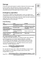
Fine tuning the flow constant - PPU
Calibration of the flow transducer is carried out with clean water but
small changes may occur when adding pesticides or fertiliser.
This will effect the final readings. This is typically noted when the
volume displayed on the display does not equal the actual known
volume that was sprayed out. The below formula can be used to
“fine tune” the flow transducer PPU.

New PPU =

  Original PPU x Displayed Volume

Sprayed Volume

For example, the spray tank is filled with 2400 litres of spray liquid.
When sprayed out, the display showed a total of 2300 litres.
(Original PPU = 120.0)

New PPU =

120.0 (Original PPU) x  2300 (Displayed Volume) = 115.0

2400 (Sprayed Volume)

Summary of Contents for HC 2500

Page 1: ...or safety 3 Description 3 Fitting the system 4 Power supply 6 Scanbox 7 Display 7 Transducer colour codes and plug assembly 8 Speed transducer 8 Flow transducer 9 Optional transducers 10 Start up 11 Reading chosen volume rate 11 HM 1500 Changing the desired volume rate for alarm 11 HC 2500 Changing the volume rate 11 Menus 13 General keystroke 13 Keystroke menu tree chart 14 Main menu 15 Display r...

Page 2: ...y Variable figures PPU Pulses per unit For flow calibration The unit measure is litre UPP Unit per pulse For speed calibration The unit measure is metre PPR Pulses per revolution For revolutions calibration BK HARDI manual control unit BK EC HARDI manual control unit with electric on off and pressure regulation EC HARDI electric control unit EVC ESC or CB Electric control unit without main valve N...

Page 3: ... the electronic components Press the keys with the underside of your finger Avoid using your fingernail If any portion of this instruction book remains unclear after reading it contact your HARDI dealer or HARDI service personnel for further explanation before using the equipment Description The HARDI Monitor 1500 and HARDI Controller 2500 are for use in agricultural and horticultural production H...

Page 4: ...t when the power is disconnected The materials and electronics for the components have been devel oped to last many years under agricultural conditions Options include a 4 20 mA transducer e g pressure revolutions transducer area meter transducer and switch box for boom sections when used with BK or BK EC control unit only for HM 1500 Fitting the system Please note the configuration and connection...

Page 5: ...witch box connector cable 9 Switch control box HM 1500 Monitor with electric control unit EC EVC ESC CB Active boom width is calculated automatically when the boom sections are operated NOTE Extended menu setting Control box is Connected ON OFF valve is Not present for EVC ESC and CB See Extended menu 1 HM 1500 display 2 Display connector cable 3 Scanbox fuse inside 4 On off switch 5 Speed transdu...

Page 6: ...ontrol box connector cable 9 Control box for electric control unit 10 Electric control unit 11 Connector cable from control unit Power supply The power supply is 12 Volt DC Brown wire is positive Blue wire is negative Power supply must come directly from the battery The wires must have a cross sectional area of at least 1 0 mm2 to ensure sufficient power supply NOTE Do not connect to the starter m...

Page 7: ... the box Fuse 1 25 T Amp Slow acting HARDI ref no 261589 The 2 pole 12 Volt socket has a maximum rating of 5 ampere Fuse 5 0 Amp Quick acting HARDI ref no 261762 Display The display is fitted in the tractor cabin at a convenient place Use only the supplied screws The mounting plate A is utilised to fit the display together with the switch box The display can also be fitted to a flat surface with V...

Page 8: ...peed flow area meter revolutions and pressure transducers Wire colour Code Connection for transducer Brown BR 12 Volt supply Black BK GND Blue BL Signal Speed transducer Speed transducer is fitted as shown Hole size is 4 5 mm Magnets must be placed an equal distance and at least 150 mm from one another Recommended number of magnets fitted are as follows Tractor front wheel rim size up to 20 4 Trac...

Page 9: ...ducer is fitted to the housing and connected to the Scanbox with the a 3 poled plug Flow transducer EC control unit 1 The distribution valve unit is detached from the main ON OFF valve unit Note the orientation of the ball seat and remove it from the distribution valve unit 2 Mount the flow transducer housing just before the distribution valves 3 Attach distribution valves with flow housing with t...

Page 10: ...h plugs and sockets is avail able HARDI ref no is 741610 Cables All the cables and wires must be routed so they do not get pinched snagged or melted The transducer cables should be shortened if necessary NOTE Although the system meets standards EN 50081 1 1992 for generic emission and EN 50082 2 1995 for generic immunity some communication systems e g 2 way radio cellular telephones may cause inte...

Page 11: ... rate press briefly either arrow keys on the display The chosen rate is shown The main picture will return again after 5 seconds or if you press accept key HM 1500 Changing the desired volume rate for alarm The desired rate must be entered if you wish to operate with the alarm Press either arrow keys on the display The rate per area is shown If the key is pressed again it will raise or lower the c...

Page 12: ...e is cleared when MAN is displayed To go from manual to automatic dosage briefly touch the arrow key on the HC 2500 Reading and reset of area trip Area trip from 1 to 8 Y can be used for individual areas Area trip 0 is a tally of area trips 1 to 8 The treated area is memorised when the system is switched off 1 Press enter key for area covered and volume sprayed 2 Press enter key again to return If...

Page 13: ...the parameter is modified press the accept key The display then changes back to the previous picture Press the accept key until the display returns to the main display There are 2 menu systems the operator menu for general use and an extended menu for initial set up of the system To access the extended menu press both arrow keys at the same time until the menu changes General keystroke Press to en...

Page 14: ...w rate Optional sensor Revolutions Speed Active boom size Flow calibration Speed calibration Revolutions Boom sections size Volume rate Tank Area 0 to 8 Flow Speed Area switch test Revolutions Optional sensor Keystroke menu tree chart Press to read or alter HC 2500 chosen volume rate Press to read or reset area trip Main menu ...

Page 15: ...e the indicated tank contents To access calibration menus To set alarm parameters To select register to record or read area covered and volume sprayed To test that the transducers function T a n k c o n t e n t s C a l i b r a t i o n A l a r m s A r e a v o l u m e t r i p S e n s o r t e s t M A I N M E N U D i s p l a y r e a d o u t ...

Page 16: ...key to continue The upper line will read DISPLAY READOUT The lower line displays the choices To show the actual application rate To show the programmed and actual application rate To show the tank contents If two tanks are used the tank contents is the total contents To show the flow rate S h o w h e r e S h o w h e r e D I S P L AY R E A D O U T V o l u m e r a t e T a n k c o n t e n t s P r o g...

Page 17: ... size Tank contents If the sprayer is partially refilled or refilled the tank contents can be adjusted See Extended menu to set tank size Press menu key and use arrow keys to raise or lower value R e v o l u t i o n s O p t i o n a l s e n s o r S p e e d A c t i v e b o o m s i z e T A N K C O N T E N T S x x x x L ...

Page 18: ...if it is fitted Boom size For setting of number of boom sections and width Correct work width for each boom section is necessary to calculate dosage and area covered Method 1 Use arrow key to set number of boom sections and press menu key Maximum number of sections is 8 Press menu key to continue For mistblowers number of sections is typically 2 2 Use the arrow key to increase or decrease section ...

Page 19: ... the values Flow constant To change the flow constant theoretically During theoretical flow calibration the number of pulses per unit are shown on the display For example 120 0 PPU indicates the number of pulses which theoretically come from the flow transducer whilst 1 litre of liquid passes through Approximate PPU values for different flow housings are as follows Housing Code for Flow range PPU ...

Page 20: ...e 2 Open all boom sections 3 Turn the main ON OFF valve on The display unit will then show the individual nozzle output per minute 4 Using a HARDI calibration jug check the actual nozzle output per minute It is recommended that an average of several nozzles be taken 5 Correct the output shown on the display with the arrow key to read the average output measured with the calibration jug The display...

Page 21: ...er until the level reaches a unique mark on the tank contents level indicator e g 1000 litres 2 Open all boom sections 3 Open menu and turn the main ON OFF valve on The display unit will then begin to count the volume being emptied through the nozzles 4 When for example 600 litres have been emptied out as shown by the tank contents level indicator the main ON OFF valve can be turned off 5 Correct ...

Page 22: ...ration of speed is done by driving a measured distance and correcting the display so that the actual and the calculated distances are the same Theoretical speed calibration should be carried out before practical speed calibration Calibration should take place in the field with a half full tank and normal working tyre pressure in order to obtain the wheel s real working radius C A L I B R A T I O N...

Page 23: ...sducer The constant pulse per revolution PPR is the number of pulses for one revolution For example if one magnet is fitted the PPR is 1 0 Alarms There are 2 alarms a tank alarm for low tank contents and a volume rate alarm for over or under application When outside the alarm parameters the relevant warning will flash A beeper can also be activated Low tank contents alarm P R A C T I C A L M e a s...

Page 24: ...de activated off by pressing the arrow key Area volume trip It is possible to choose up to 9 area trip meters 0 to 8 Area 0 is a total for all areas treated When any of the other areas are used the treated area and volume will also be registered automatically in Area 0 For reset of Area Volume Trip see Reset of area trip A c t i v a t e d a t x x A u d i o o f f A c t i v a t e d a t x x A u d i o...

Page 25: ...e transducer from flow housing and spin rotor Every second magnet will give a count indicating correct function See also Testing flow transducer To test the speed sensor Every magnet will give a count indicating correct function See also Testing speed transducer To test the area meter switch Without magnet S E N S O R T E S T F l o w t e s t S p e e d t e s t D r i v e s l o w l y x x x A r e a s ...

Page 26: ...ing a HM 1500 with manual control unit and switch box or HC 2500 with EC control box all the switches must be turned on If you do not want to utilise the area meter transducer the main on off switch can be used to start and stop the area register Mistblowers and HM 1500 HC 2500 Points to note if the system is used on a mistblower Work width is the same as the spray width of the mistblower Not acti...

Page 27: ...y cabling and No bip sound at start up connections Displayed area larger Field was not rectangular than actual area Tramlines narrower than Measure tramline width spray width Displayed volume larger Pressure equalisation valve Replace seals than actual volume leaks Fine tuning the flow constant PPU Calibration of the flow transducer is carried out with clean water but small changes may occur when ...

Page 28: ...ts are N S N S 4 Connect negative from multimeter to negative of battery 5 Set multimeter to DC volt 6 By turning the mill wheel slowly this will register approx 8 0 1 volt with the diode on and 0 3 0 1 volt with the diode off with every second magnet Testing speed transducer Ref no 729058 Wire connections BROWN wire to positive of 12 volt battery BLACK wire to negative BLUE wire to multimeter 1 C...

Page 29: ...fice Flow White 13 5 mm 5 to 150 l min Black 20 0 mm 10 to 300 l min One outside groove 13 5 mm 5 to 150 l min Two outside grooves 36 0 mm 35 to 600 l min Pressure drop over 13 5 mm orifice is 1 bar at 150 l min Packaging information Materials used for packaging are environmentally compatible They can be safely deposited or they can be burnt in an incinerator Recycling Cardboard Can recycle up to ...

Page 30: ...F valve To select EC or EVC ESC CB control unit Present not present Pressure system To select pressure system Equalisation No equalisation Control box To indicate control box connection to Scanbox Connected Not connected Tank volume max To pre set tank volume indicated at start up Analog adjust To calibrate the optional transducer max min offset in mA Analog unit text To choose the unit of measure...

Page 31: ...n 0 offset in mA 0 mA offset in mA 0 mA Analog unit text Bar Bar Regulation con 0 0 Flow PPU 120 0 120 0 Speed UPP 1 0000 1 0000 HC 2500 For EVC ESC or CB control unit set ON OFF valve to Not present HM 1500 For BK BK EC or EC control unit with switch control box for boom sections set Control box to Connected For EVC ESC or CB control unit set ON OFF valve to Not present Control box to Connected N...

Page 32: ...clare that the following product Adhere extra shipping package labels to inside cover was manufactured in conformity with the provisions in the EMC direc tive 89 336 EEC EN 50081 1 1992 generic emission and EN 50082 2 1995 generic immunity Taastrup 15 09 2002 Lars Bentsen Product Development Manager HARDI INTERNATIONAL A S ...

Page 33: ...33 ...

Page 34: ...34 ...

Page 35: ...35 ...

Page 36: ...36 ...

Reviews: