4
Functions include correct area with closure of up to 8 spray boom
sections, alarm functions for dosage and minimum tank contents and
possibility for audio/visual alarm.
The transducers utilised are chosen for long service life and good
signal quality. Speed, area switch and revolutions transducer is the
same component. The flow transducer has a diode built into the
housing to aid servicing. As the rotor turns, the diode will flash thereby
indicating it functions.
The system has a non-volatile memory with no battery which simplifies
storage. All parameters in the menus are saved in the display’s
memory and are not lost when the power is disconnected.
The materials and electronics for the components have been devel-
oped to last many years under agricultural conditions.
Options include a 4-20 mA transducer (e.g. pressure), revolutions
transducer, area meter transducer and switch box for boom sections
when used with BK or BK/EC control unit (only for HM 1500).
Fitting the system
Please note the configuration and connections for your system.
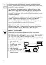
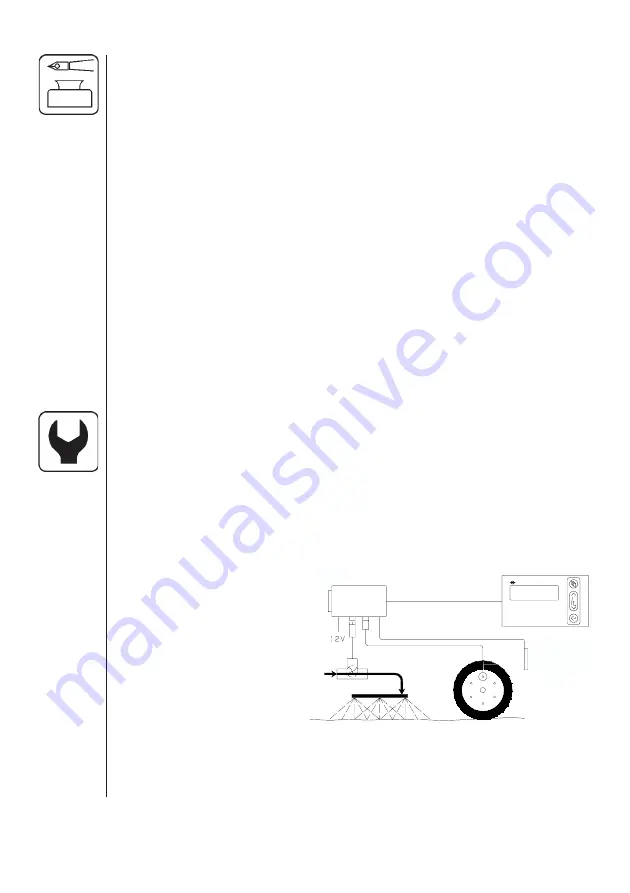
HM 1500 Monitor with manual control unit (BK, BK/EC)
The active boom width is always the total boom width.
The system can not automatically calculate correctly when one or more
boom sections are turned off.
1.
HM 1500 display
2.
Display connector cable
3.
Scanbox (fuse inside)
4.
On/off switch
5.
Speed transducer
6.
Flow transducer
7.
To 12 Volt power supply
8.
Switch box connector
cable (not used)
1.
2.
3.
4.
5.
6.
7.
8.

