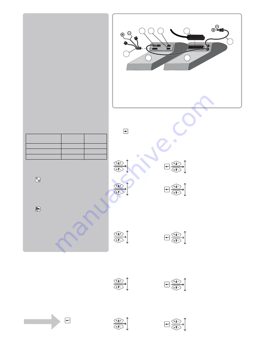
12 V
D
E
A
B
F
12 V
G
C
H
Menu tree
The first steps to select a menu are shown below.
Press
to proceed into the menu.
See the relevant section in the instruction book.
Press ESC and hold to exit the menu system.
5 LOGBOOK
5.1 Print
5.2 Data dump
4.1 Measure
4.2 Service intervals
4.3 Stop watch
4.4 Alarm clock
4.5 Test
4.6 Speed simulation
3.1 Speed
3.2 Flow
3.3 Boom
3.4 Regulation constant
3.5 Tank gauge
2.1 Display readout
2.2 AUTO functions
2.3 VRA/Remote
2.4 Set clock
2.5 Alarms
2.6 Register names
1.1 Volume rate
1.2 Tank contents
1.3 Select register
4 TOOLBOX
3 CALIBRATION
2 SETUP
1 DAILY SETTINGS
Basics to get going
Boom data, spray flow, volume rate and speed
calibration must be entered.
Go to the menu on the Controller and find the
relevant section in the instruction book.
Boom data
[3.3.1 WIDTH]
[3.3.2 NUMBER OF SECTIONS]
[3.3.3 NOZZLES PR. SECTION]
Flowmeter calibration
[3.2.1 FLOW CONSTANT]
The below PPU value is approximate and a
practical calibration is recommended.
The standard values for HARDI flow housing are:
Volume rate
Press
and hold until
[1.1 VOLUME RATE] is shown.
Speed calibration
Press
and hold until one of the following is
shown:
[3.1.1 Sprayer] Speed sensor on sprayer
[3.1.2 Tractor] Speed sensor on tractor
[3.1.3 Radar] Speed sensor is a radar
The practical calibration is recommended.
One outside
groove
No outside
groove
Orifice (mm)
13.5
20.0
Flow range (liter/minute) 5 to 150
10 to 300
Approx. PPU
120.00
60.00
Connections
A.
Controller
B.
Spray box
C.
Cable from Spraybox
D.
COM 1
E.
COM 2
F.
AUX Cable -12 Volt (optional)
G.
Cable from junction box
H.
Power - 12 Volt
Main menu
Start screen


