background image

7

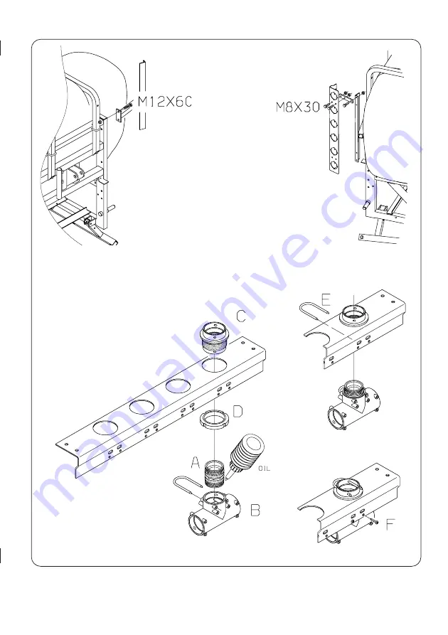
8. Mount MANIFOLD fittings

(and eventual valves). Now bolt
bracket to the left hand side.

Summary of Contents for Master-MA Series

Page 1: ...Master MB Assembly Instruction 672203 GB 96 11 ...

Page 2: ...e the protection film on top of the CE mark NOTE The self adhesive CE mark and protection film needs to harden for 24 hours 4 Fill in the customer file with customer name address and sprayer data full description shipping packages and shop order numbers Each shipping package contains two labels with the number of the package One label is for the customer file as described the other is for the inst...

Page 3: ...ineral lubri cant before assembly Model 1202 1302 2 Tee with O ring and pressure damper are fixed to the frame Tee with O ring and suction damper are mounted to the pump Elbow and nipple are mounted to pressure outlet Use sealing tape Turn elbows to the left Fit pump to base plate Use staggered brackets ...

Page 4: ...4 Model 361 2 Elbow is mounted to suction inlet Elbow and nipple are mounted to pressure outlet Use sealing tape Turn elbows to the left Fit pump to base with M10 x 20 bolts B ø 30 x 26 x 2 O ...

Page 5: ...nt rotation of the protec tive guard For conical connection recheck the grub screw is tight after 5 min of usage Level indicator 4 Tube holders and tube are fitted With the float resting on the stop pin at the bottom of the rod the O ring on the indicator must be positioned at the top position line A Remove plug B and loosen screws C to alter position B A C ...

Page 6: ...e in the agitation valve and fit the assembly 7 See back of pressure gauge Pierce casing and fit gauge Use sealing tape Do not overtighten BK operating unit 5 Place ball in the main ON OFF valve and turn the handle so the ball disappears Fit valve seat and connect main valve to the distri bution valves ...

Page 7: ...7 8 Mount MANIFOLD fittings and eventual valves Now bolt bracket to the left hand side ...

Page 8: ...p to pressure damper C From main ON OFF to tank D From agitation valve to tank E From pressure equalization to tank F From distribution valves to boom Shortest for centre inner section H From HARDI MATIC to tank K From pressure manifold to safety valve M From pressure mainfold to operating unit N From Self Cleaning Filter if fitted to tank Use green restrictor for initial setup O From suction mani...

Page 9: ...f good order it may be necessary to shorten some hoses This is best done when assembly is completed and before hoses are se cured with plastic straps 13 Bolt step and hose holder to the right hand side 12 Fit Self Cleaning Filter to right hand side tank brace Use green restrictor for initial setup ...

Page 10: ... spacer and secure with split pins Fit the 4 bolts to the lift wagon but do not tighten Lower wagon down the gantry Fit the pin and secure with split pins Adjust glide pads A so distance B is equal Lubri cate glide pads B A 15 Fit bridge and centre part ...

Page 11: ...11 15a Fit rear nozzle holder 16 Lock the trapeze and fit boom wings Easiest with 2 persons 17 Fit outer section locks Do it with the boom unfolded to ensure the pins and holes line up ...

Page 12: ...pplied with one lock nozzle saddle per tube A The rest can slide lengthwise B allowing for extension and contraction Tubes and hoses are connected REMEMBER Lubricate O rings before fitting Use non mineral lubricant Fit tubes using synthetic nut Press down 1 turn 2 Do not overtighten Fit filter and COLOR TIP A B ...

Page 13: ...that hoses do not catch or pinch whilst raising lowering or folding unfolding the boom Organize hoses in tidy bundle may be necessary to shorten some and secure in brackets and with straps Pressure check the sprayer with clean water See Anti freeze precautions in the instruction book if the sprayer is not stored frost free ...

Page 14: ...14 ...

Page 15: ...15 Notes ...

Page 16: ...16 ...

Reviews: