4 - Sprayer setup
32
Liquid system
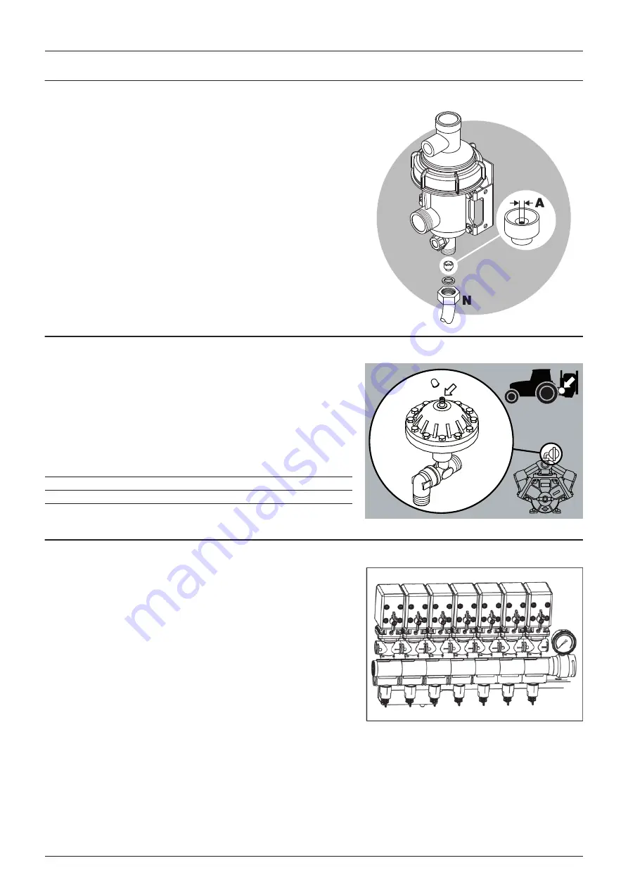
Self-cleaning filter - Choice of restrictor
It is important to have a large flow through the filter. This is achieved by
choosing the restrictor size in relation to the liquid consumption of the
spray boom. 4 restrictors are supplied. Use the green one with largest
orifice (A) first.
Remove the hose (N) from the filter. Be careful not to loose the seal. Place
the restrictor in the hose and mount the hose again.
If the required working pressure cannot be obtained, the restrictor is too
large. Choose a smaller restrictor. Start with a black one, then a white and
finally a red one.
When cleaning the filter, remove hose (N) and the hose at the safety
valve and check that there are no residues.
Standard filter size is 80 mesh. Filters of 50 and 100 mesh are available
and can be changed by opening the filter top. Check condition of O-
rings before reassembly and replace if damaged.
Pulsation damper (if fitted)
The air pressure in the pulsation damper is factory preset at 2 bar to
cover spray working pressures between 3 and 15 bar.
When using spray pressures outside this range, the air pressure should
be adjusted as shown in the diagram. The diagram is embossed on the
damper.
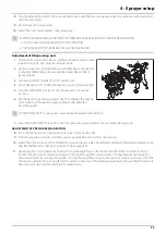
Adjustment of EVC operating unit
Adjust the EVC operating unit before spraying, using clean water
(without chemicals).
1.
Choose the correct nozzle for the spray job by turning the TRIPLET
nozzle bodies. Make sure that all nozzles are of the same type and
capacity. See the “Spray Technique” book.
2.
Set the main ON/OFF switch to ON at the spray control unit.
3.
Turn all distribution valve switches ON at the spray control unit.
4.
Press down the pressure regulation switch at the spray control unit
until the emergency handle on the valve stops rotating (minimum
pressure).
5.
Put the tractor in neutral and adjust the P.T.O. and thereby the
number of revolutions of the pump corresponding to the intended travelling speed. Remember to keep the number
of revolutions of the P.T.O. between 300-600 rpm (pump 540 r/min) or 650-1100 rpm (pump 1000 r/min).
6.
Press up the pressure regulation switch at the spray control unit until the required spray pressure is shown on the
pressure gauge.
ADJUSTMENT OF PRESSURE EQUALIZATION:
7.
Close the first section valve on the spray control unit.
Spray Pressure (Bar)
Damper pressure (Bar)
1.5 - 3
0 - 1
3 - 15
1 - 3
15 - 25
3 - 4
Summary of Contents for MASTER PRO VHH
Page 6: ...Table of Contents 6 ...
Page 8: ...1 EC Declaration 8 ...
Page 12: ...2 Safety notes 12 ...
Page 50: ...5 Operation 50 ...
Page 52: ...6 Maintenance 52 Boom lubrication oiling plan Lift lubrication oiling plan ...
Page 70: ...7 Fault finding 70 ...
Page 76: ...8 Technical specifications 76 Charts Boom hydraulic Z ...
Page 78: ...8 Technical specifications 78 ...
Page 82: ...HARDI INTERNATIONAL A S Helgeshøj Allé 38 DK 2630 Taastrup DENMARK ...

