GB 14 02 02 MA
Maintenance
F
FF
F
F
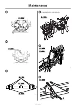
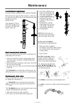
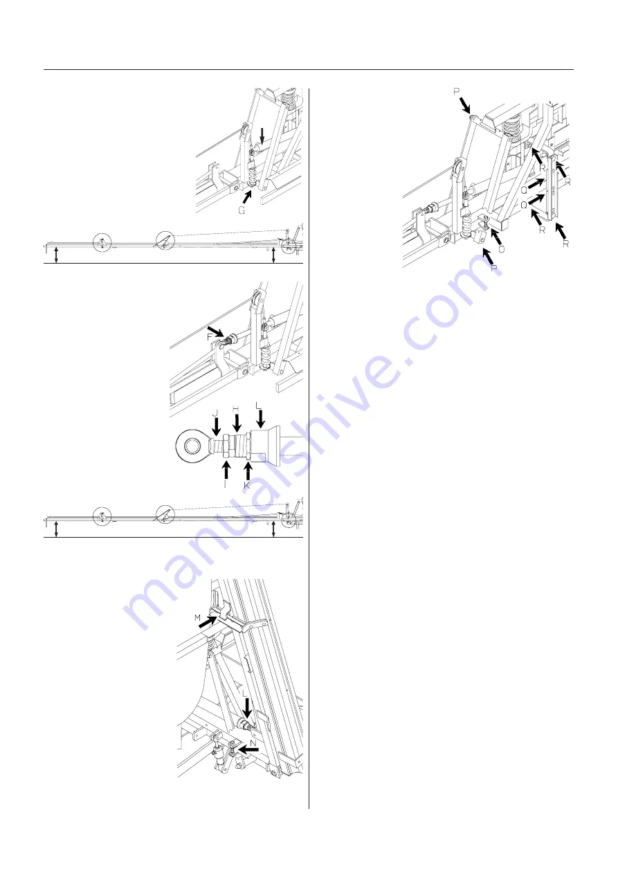
4. Wire
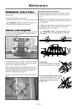
The wire function is to carry the boom
wings. Adjustment of the wire should be
undertaken with the boom unfolded
and the hydraulic rams
F
discon-
nected from the boom wings.
Tighten nut
G
so that the tip is
raised 12 cm for the 12 m boom
and 15 cm for the 15 m boom
from the horizontal line of the
centre section.
5. Parallel adjustment of inner section
1. Cautiously activate the hydraulic rams
F
so they are fully extended. Make
sure the extension
H
is screwed
in and tight.
2. Loosen counter nut
I
and adjust the ram eye
J
so that when connected,
the boom wings are
parallel with the centre
section. The ram must
force the boom tip down
so distance “X” is equal.
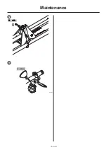
6. Adjustment for transport brackets
and air stream angle
Fold boom and lower cautiously into
transport brackets. Loosen coun-
ter nut
K
and adjust
L
so the
boom rests in the middle of
the brackets.
When the boom is lowered,
it must be firmly hooked onto
the transport bracket
M
.
Loosen counter nuts and
adjust bolt
N
so that the
boom hooks firmly into place
without exerting excessive
force on the boom wings.
Unfold the boom. Loosen
counter nut and screw bolt
O
in fully. Set air stream to
angle forward so the ram is
fully extended. Now adjust
bolt
O
up to the stop and turn furthermore ” a turn.
X + 12/15 cm
X cm
7. Trapeze suspension
For the trapeze to function it
must not be to tight. If it is to
loose the boom will yaw
(forward and back move-
ment). This results in a poor
spray distribution.
Adjust tension
P
so
the boom is not
too tight nor too
loose. Minor
adjustment in the
field may be
necessary.
Check distance
Q
.
The synthetic pads
should only just touch the centre beam. Relocate wash-
ers on each of the 4 bolts
R
if the distance is excessive.
IMPORTANT!
Check all counter nuts are tight after
adjustment.
Changing of
Changing of
Changing of
Changing of
Changing of v
v
v
v
valv
alv
alv
alv
alves and dia
es and dia
es and dia
es and dia
es and diaphr
phr
phr
phr
phra
aa
a
agms
gms
gms
gms
gms
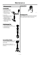
Access to the pump is best from the rear of the sprayer.
A “
S
” shaped hook supplied with the sprayer is used to
mechanically secure the boom from lowering whilst
servicing the pump. Raise the boom with the hydraulic
boom lift and use the hook as shown.
X cm
X cm
WARNING!
Always secure
the boom before
servicing the
pump.
NOTE!
For
servicing model
361 pump, it is
best to remove
the lower anchor
bolt of the lift ram
and push the ram
over to one side.

