4 - Sprayer setup
51
Parallel setting of lift and frame
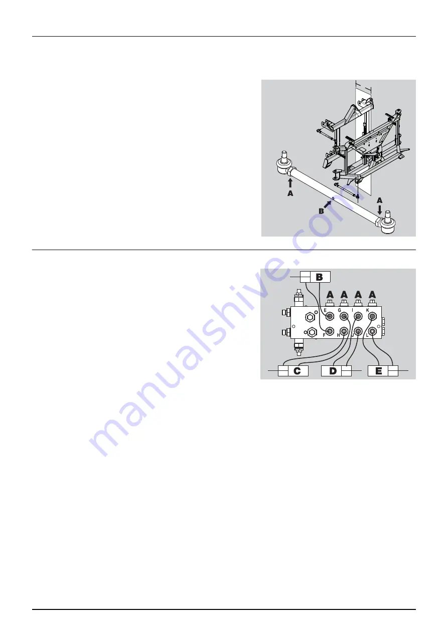
The lift frame and the pendulum must be parallel positioned (C). If necessary, the length of the 4 steering arms can be
adjusted to obtain parallel setting (C).
Adjustment of each steering arm is performed as follows:
1.
Loosen nuts (A).
2.
Place a suitable tool (e.g. a screwdriver) in the hole (B) in the turn
buckle, and use the tool to rotate the turn buckle.
Clockwise rotation: The turnbuckle becomes shorter and the
distance between centre section and lift/trailer decreases.
Counterclockwise rotation: The turnbuckle becomes longer and
the distance between centre section and lift/trailer increases.
3.
When correct setting has been obtained, tighten nuts (A) on the
turnbuckle again.
μ
ATTENTION! The distance must be uniform on both upper and
lower frame part, and the distance should be in the span 175-185
mm. Measure the distances to control the uniformity!
Boom folding speed adjustment - LPY only
Adjustable restrictors for the regulation of boom folding and unfolding
speed, are located on the hydraulic distribution block (fitted at the
boom centre frame). It is important to adjust the valves to ensure that
the boom operates smoothly.
1.
Adjust the 4 screws (A). They are screwed the whole way in
clockwise, and then 1 turn back. The system is now basically
adjusted.
2.
Unfold and fold the boom several times in order to heat the oil and
remove air from the system.
3.
Adjust the screws (A) until the individual rams run with the speed
wanted (clockwise = less speed).
μ
ATTENTION! The system must not be pressurized during adjustment.
€
DANGER! Test of the hydraulic system should be done very cautiously. There may be air trapped in the system which
can cause violent movements of the boom.
€
DANGER! Hydraulic leaks: Never use your fingers to locate a leakage in any part of the hydraulic system. Due to high
pressure, hydraulic oil may penetrate the skin.
C
Summary of Contents for NAVIGATOR DELTA
Page 4: ...1 EC Declaration 4 ...
Page 10: ...Table of Contents 10 ...
Page 14: ...2 Safety notes 14 ...
Page 32: ...3 Description 32 ...
Page 54: ...4 Sprayer setup 54 ...
Page 74: ...5 Operation 74 ...
Page 76: ...6 Maintenance 76 Boom lubrication oiling plan ...
Page 104: ...7 Fault finding 104 ...
Page 120: ...HARDI INTERNATIONAL A S Herthadalvej 10 DK 4840 Nørre Alslev DENMARK ...

