


3 - Description
47
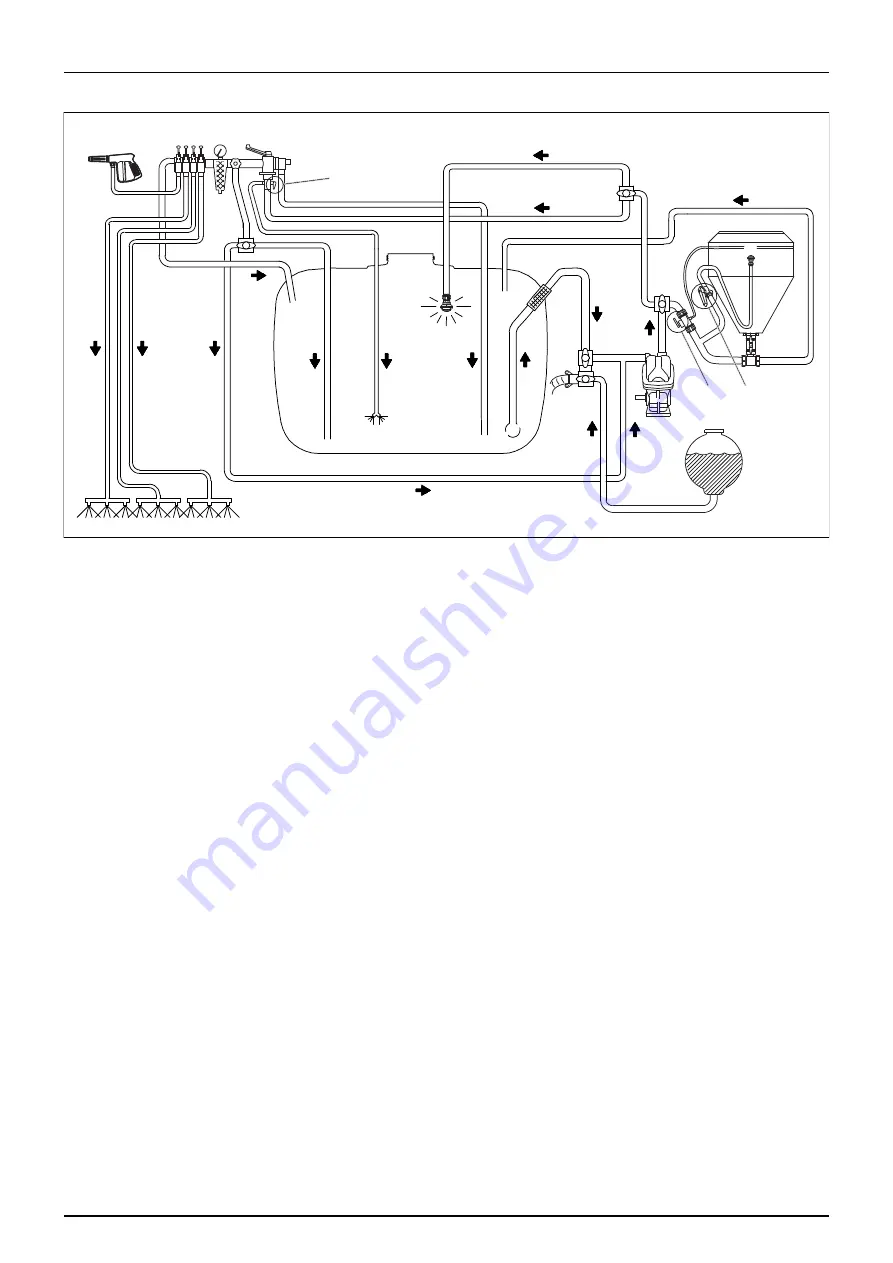
Diagram - Liquid System with Options (BK Operating Unit)
1.
Pump
2.
Main Tank
3.
Suction Valve
5.
Pressure Valve
6.
Pressure Filter
9.
Distribution Valves
10.
Pressure Gauge
12.
Spray Boom
13.
Agitation Valve
14.
Agitation Nozzles
15.
Return Line for Main Tank
19.
Rinsing Nozzle
20.
Rinse Tank
33.
External Cleaning Valve and Spray Gun
46.
Pressure Regulation
48.
External Filling Device Valve
52.
Return Line - Pressure Equalization
53.
Suction Filter
66.
Main ON/OFF Valve
68.
Return Valve
69.
ChemFiller Cleaning Valve
70.
ChemFiller Flush Valve
71.
ChemFiller Suction Valve
72.
ChemFiller ON/OFF Valve
46
72
66
52
68
53
33
70
69
71
19
20
15
14
1
2
9 10
6
12
3
5
13
48
Summary of Contents for NK SB Series
Page 8: ...1 Identification 8...
Page 52: ...3 Description 52...
Page 62: ...4 Sprayer Setup 62...
Page 84: ...5 Operation 84...
Page 87: ...6 Maintenance 87 Boom Lubrication Oiling Plan Lift Lubrication Oiling Plan...
Page 116: ...9 EC Declaration 116...
Page 120: ...Index 120...
Page 122: ...HARDI INTERNATIONAL A S Helgesh j All 38 DK 2630 Taastrup DENMARK...


