background image

5 - Operation

53

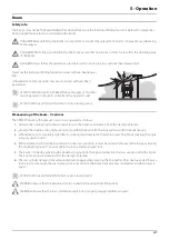
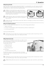
Parking the sprayer

To avoid spot contamination the sprayer should always be parked at either the washing/filling place or under roof. This avoid 
rainfall to flush down chemical residues from the sprayer's surfaces. 

Parking at the washing/filling location will retain residues.

Always park the machine out of reach of children, animals or unauthorized persons.

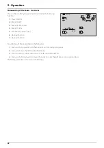
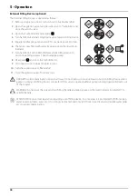
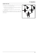
Operating the control unit while spraying

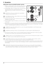
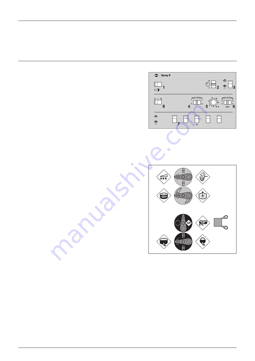
The switches of the spray control unit control the following functions:

1.

Power ON/OFF. Turns the spraybox power on or off.

2.

Spray pressure regulation. Regulates the main spray pressure.

3.

Main valve ON/OFF. Turns all sections on or off. Lever up is OFF and 
down is ON.

4.

End nozzle (Left/OFF/Right). If end nozzles are fitted, they can be 
turned on for each side. Middle position is OFF.

5.

Foam marker blob interval. Regulates the blob interval for the 
optional foam marker.

6.

Foam marker (Left/OFF/Right). Turns the optional foam marker on for each side. Middle position is OFF.

7.

Section valves. Turns single sections on or off. Lever up is OFF and down is ON.

8.

Optional function (A/OFF/B). If extra equipment is added, it can be controlled from here. Middle position is OFF.

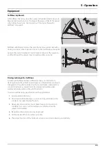
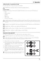
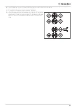
In order to close the entire boom, switch main ON/OFF (3) to OFF 
position. This returns the pump output to the tank through the 
return system. The diaphragm Non-drip valves ensure 
instantaneous closing of all nozzles.

In order to close one or more sections of the boom, switch the 
relevant distribution valve (7) to off position (upwards). The 
pressure equalisation ensures that the pressure does not rise in the 
sections that remain open.

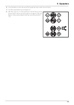
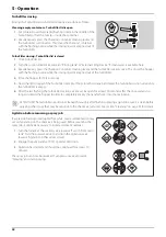
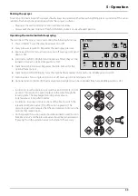
On the sprayer the suction valve should be turned toward “Suction 
from Main tank” and the pressure valve should be turned toward 
“Spraying”. Turn the agitation valve to “Agitation” if necessary.

Summary of Contents for RANGER EAGLE

Page 1: ...RANGER EAGLE Original Instruction book 67009300 110 Version 1 10 GB 06 2013 www hardi international com ...

Page 2: ...ok are to the best of our belief correct at the time of printing As it is HARDI INTERNATIONAL A S policy permanently to improve our products we reserve the right to make changes in design features accessories specifications and maintenance instructions at any time and without notice HARDI INTERNATIONAL A S is without any obligation in relation to implements purchased before or after such changes H...

Page 3: ... 23 Boom and terminology 23 Equipment 24 SelfSteer optional 24 Step 24 Platform 24 Tank level indicator 25 Nozzle pressure gauge 25 Safety locker optional 25 External Cleaning Device optional 25 4 Sprayer setup General info 27 Before putting the sprayer into operation 27 Unloading the sprayer from the truck 27 Support leg 27 Jack up the sprayer 28 Transmission shaft 29 Operator safety 29 P T O ins...

Page 4: ...er optional 50 TurboFiller rinsing 52 Agitation before resuming a spray job 52 Parking the sprayer 53 Operating the control unit while spraying 53 Quick reference Operation 54 Cleaning 55 General info 55 Quick reference Cleaning 56 Cleaning the tank and liquid system 56 Cleaning and maintenance of filters 57 Use of rinsing tank and rinsing nozzles optional 57 BoomFlush optional 58 Technical residu...

Page 5: ...ion shaft 74 Replacement of transmission shaft cross journals 74 Change of bulbs 74 Change of tyre 75 Wear bushing renewal on steering 75 Safety valve activation 75 Slanting indicator adjustment optional 75 Readjustment boom general info 76 Alignment of centre and inner wing sections 76 Alignment of inner and outer wing sections 77 Breakaway section adjustment 77 Adjusting the front fold cable 78 ...

Page 6: ...s 90 Filters and nozzles 90 Tyre specifications 90 Temperature and pressure ranges 91 Materials and recycling 92 Disposal of the sprayer 92 Electrical connections 93 Rear lights 93 Electrical connections for SPRAY II 93 EVC junction box 94 Charts 95 Boom hydraulic Z 95 Boom hydraulic Y 95 Index Index 97 ...

Page 7: ... declare that the following product s Fulfils all the relevant provisions of Machinery Directive 2006 42 EC 2009 127 EC and later amendments All the relevant provisions of Council Directive 2004 108 EC EMC Taastrup 02 05 2011 Lars Bentsen Vice president Product development HARDI INTERNATIONAL A S RANGER EAGLE SPB Y SPB Z and SPC Y SPC Z ...

Page 8: ...1 EC Declaration 8 ...

Page 9: ... certified to use spray equipment Adhere to the law Tractor driver s seat is the intended working place during operation Wear protective clothing Clothing may differ depending on chemical being sprayed Adhere to local law Wash and change clothes after spraying Wash tools if they have become contaminated Do not eat drink or smoke while spraying or working with contaminated equipment In case of pois...

Page 10: ...places on the machine Anybody working with or being in close range of the sprayer must respect these labels The labels should always be clean and readable Worn or damaged labels must be replaced with new ones Contact your local dealer for new labels Note that not all labels shown here will apply to your sprayer Tank under pressure Beware when moving lid Grapping area Manual handling of boom etc Se...

Page 11: ...vice Tighten with torque according to instruction book Risk of falling off Do not ride on platform or ladder Risk of injury Keep hands away Risk of sprayer tipping over Be aware when disconnecting the sprayer Risk of injury Do not open or remove safety shields while engine is running Risk of burn Stay clear of hot surfaces Risk of squeeze Keep hands away when parts are moving Risk of injury Flying...

Page 12: ...2 Safety notes 12 ...

Page 13: ...y μ ATTENTION Max driving speed for models without brakes and for models equipped with brakes is different Be aware that these speeds may differ due to local law Contact local authorities for information of max driving speeds Tanks and equipment The main tank made of impact proof UV resistant and chemical resistant polyethylene has a purposeful design with no sharp corners for easy cleaning The fi...

Page 14: ...gauge 4 SafetyLocker 5 Support leg 6 Pump 7 Hitch 8 Step 9 Suction filter 10 Suction valve 11 External Filling Device valve 12 Agitation valve 13 Pressure valve 14 Cyclone filter 15 TurboFiller valves 16 TurboFiller 17 Rinse tank lid 18 Drain valve handle 19 Clean water tank lid ...

Page 15: ...3 Description 15 20 Distribution valves 21 Main tank 22 External Cleaning Device hose reel 23 Handbrake 24 Air brakes tank ...

Page 16: ...nd max pressure of the spray liquid system Frame boom centre frame and other main steel components have identification plates indicating type and part number not illustrated REFERENCE NO is the main reference number of the complete machine CE identification plate fitted on the frame indicates producer name model and a serial number for the sprayer HARDI INTERNATIONAL AS REFERENCE NO ...

Page 17: ...ntenance for further information A Pressure valve This valve is to select which function the pressurized liquid from the pump will be routed to The active function is indicated by the indicator The handle is turned so the indicator points to the label for required function If handle is turned to a position without label unused function then the valve is closed B Agitation valve With the adjustable...

Page 18: ...Activating valve starts stops the filling proces Note that the suction valve must be closed for maximum filling capacity D Suction valve This valve is to select from where the pump sucks the liquid The handle is turned so the label for required function is directed to the indicator If handle is turned to vertical position indicator not pointing at a label then the valve is closed Suction from exte...

Page 19: ...n the number of P T O revolutions are between 300 600 r min EVC control unit EVC Electrical Valve Control The ON OFF is linked to the section valves which results in a very quick response to ON OFF The operating unit is of modular design and is electrically controlled via a remote control box The unit has a built in HARDI MATIC Filters A suction filter is fitted on the sprayers left side just in f...

Page 20: ...lter is going to be clogged when spraying This position is used when rinsing the boom if the main tank is empty C This position marked with 3 dots Flushing position which is used if filter is clogged Lift and hold the lever to use this position which largely increases return flow and flushes the filter The top green pressure valve must be set to Spraying μ ATTENTION Use of position C is no guarant...

Page 21: ...d transferred to main tank TurboDeflector valve This TurboDeflector valve activates the Vortex flushing of the TurboFiller Lift the lever to lock it in open position for continuous liquid rotation in the hopper Chemical Container Rinsing lever The upper lever is used for two purposes When the TurboFiller lid is open For rinsing empty containers Place the container over the rotating flushing nozzle...

Page 22: ... 9 CycloneFilter optional 10 On Off Purge valve 11 One way valve 12 Distribution valves 13 Distribution boom 14 Rinsing tank 15 External Filling Device coupler optional 16 TurboFiller optional 17 TurboFiller valve panel 18 Pressure gauge 19 Agitation 20 Rinsing nozzle optional 21 Return from distribution valves 22 Drain valve 23 Main tank pressure inlet 24 Spray lance On Off 25 Spray lance for Ext...

Page 23: ...ndirect Acting Hydraulics named SPB SPC Y Operated via the tractor hydraulics Hydraulic lift cylinder for boom height adjustment Two cylinders for simultaneous boom wing fold and unfold Slant is optional equipment which is operated directly by the tractor hydraulics SPB SPC Z Same features as the above mentioned Y models but are provided with more advanced hydraulics controlled via a hydraulic con...

Page 24: ...on headland Further the SelfSteer can be with SlopeCorrection It has same function as the normal SelfSteer but can also be used for track correction on slopes to help the SelfSteer to stay in the tramline also in hilly conditions μ ATTENTION The SlopeCorrection is operated with the tractor s hydraulic control lever Step A step is located on the left side of the sprayer frame for easy access to the...

Page 25: ...ety locker is for storage of safety gear such as non contaminated protective gear soap for hand washing etc The locker is split in two compartments for the separation of clean clothes and contaminated equipment WARNING Although this locker is meant for the storing of non contaminated items it must neverbe used for the storing of food beverage or other items meant for consumption External Cleaning ...

Page 26: ...3 Description 26 ...

Page 27: ... when the tanks are empty Support leg Depending on whether the sprayer have SELF STEER or not the support leg may differ NOTE The support leg and jack capacity is sufficient to carry the drawbar weight with full tank on level ground Without SELF STEER The support leg is stored in retracted horizontal position and secured by the lock pin when the sprayer is attached to the tractor How to place spra...

Page 28: ...ng wheel changing brake or wheel bearing changing etc then jack up the sprayer under the axle as shown DANGER Be sure to place sprayer at level and firm ground to avoid sprayer falling down from the jack μ ATTENTION It is good practice to use stop wedges at the opposite wheel ...

Page 29: ...enance or repairs to the transmission shaft or implement DANGER ROTATING TRANSMISSION SHAFTS WITHOUT PROTECTION GUARDS ARE FATAL P T O installation Always read the manufacturer s instruction book before applying any installation of the transmission shaft First installation of the transmission shaft is done in the following way 1 Attach the sprayer to the tractor and set the sprayer height in the p...

Page 30: ...rayer the rods must be turned from position B to position A Rod positions A Spraying B Driving on public roads DANGER When driving on public roads the rods must be fitted in position B Failure to do so may cause the sprayer tipping over in turns or curves When connecting the SelfSteer with SlopeCorrection the rod must be removed from position D and stored in position B The hydraulic cylinder must ...

Page 31: ...m The bracket is for the storing of hydraulic and electric connectors etc when the sprayer is disconnected from the tractor The height of the bracket can be adjusted by the means of the bolts B μ ATTENTION Check that the length of the hoses and cables are sufficient by tight turns μ ATTENTION A sprayer with SelfSteer requires more slack in the cables Make sure cables are long enough in tight turns...

Page 32: ...n of the spray boom One double acting outlet for the folding function Z model requirements One double acting outlet for the electro hydraulic operation of the boom functions General Ensure that snap couplers are clean before connection The hydraulic system requires a minimum oil pressure of 130 bar max oil pressure of 210 bar and an oil capacity of approx 25 litres WARNING Due to the variation in ...

Page 33: ...ction WARNING Before operating the hydraulics the valve should be set according to the specific tractor model If you are unsure of the type of hydraulic system in your tractor please contact your tractor dealer Combinations of settings for flow element and circuit value if tractor requires pressure relief contact your tractor dealer for further advice WARNING Always be sure to fully open or close ...

Page 34: ...e hidden behind front corner cover Check tractor instructions manual for information regarding attachment points Three mounting tubes B are supplied One two or all three may be used They can be bent and shortened A spacer C is also supplied to allow further attachment possibilities Find the best solution for your tractor or vehicle Tube B plate is staggered so that if correctly orientated all boxe...

Page 35: ...ow A follows the forward rotation of the wheel μ Adjust so the sensor lines up in the middle of the gaps in vertical direction ATTENTION If necessary readjust plate on the axle 2 Adjust air gap B to 3 0 0 2 mm Use 3 0 mm feeler gauge or similar tool NOTE Adjustment shall be made out of one of the carriage bolts for the speed ring 3 After adjustment then spin up the wheel Verify air gap variation l...

Page 36: ...eed to be adjusted inwards or outwards 3 Relieve the pressure from the fold cylinder by unfolding the boom a few centimetres 4 If the boom rests to far in on the transport brackets loosen the counternut B and adjust collar A in towards the cylinder housing 5 If the boom rests too far out on the transport brackets the collar A has to go out from the cylinder housing 6 Secure counternut B 7 Pressuri...

Page 37: ...ive Narrower B Positive Wider Free hubs Brake hubs Track width mm X dimension mm Rim mounting position Track width mm X dimension mm Rim mounting position 1520 835 A 1500 825 A 1570 860 A 1550 850 A 1620 885 A 1600 875 A 1642 735 B 1650 900 A 1670 910 A 1700 925 A 1692 760 B 1750 950 A 1720 935 A 1800 975 A 1742 785 B 1822 825 B 1770 960 A 1850 1000 A 1792 810 B 1872 850 B 1820 985 A 1900 1025 A 1...

Page 38: ...e brake operating arm 6 Extend or retract the axle A sack barrow and a rod will facilitate the operation 7 Tighten the clamp bolts A to a torque of 250 Nm 8 Repeat the procedure on RH wheel 9 Check if the distance from centre tyre to centre of rear frame is equal at RH and LH 10 Retighten bolts and wheel bolts to specified torque after 8 hours of work μ ATTENTION The wider the track width the bett...

Page 39: ... and thereby the number of revolutions of the pump corresponding to the intended travelling speed Remember to keep the number of revolutions of the P T O between 300 600 rpm pump 540 r min or 650 1100 rpm pump 1000 r min 6 Press up the pressure regulation switch at the spray control unit until the required spray pressure is shown on the pressure gauge ADJUSTMENT OF PRESSURE EQUALIZATION 7 Close th...

Page 40: ...4 Sprayer setup 40 ...

Page 41: ... the single acting hydraulic outlet to raise the boom and release it from the transport brackets 2 Activate the double acting hydraulic outlet to unfold the boom Both wings will now unfold simultaneously 3 When the boom is completely unfolded it can be raised or lowered to the desired spray height by activating the single acting hydraulic outlet 4 Before attempting to fold the boom back into trans...

Page 42: ...h sides 6 Optional function 7 Optional function For unfolding of the boom then do the following 1 Push switch 3 upwards to lift the boom clear of the transport brackets 2 Push switch 5 to the left to unfold the boom 3 Push switches 2 and 4 downwards to lower individual tilt rams 4 Push switch 3 downwards to lower the boom to correct height above crop or ground level The folding procedure is the re...

Page 43: ...aves differently than a normal trailer In tracking position the vehicle centre of gravity is displaced more outward compared to the vehicle centre line of a normal trailer Compared to a conventional trailer a steered trailer has decreased stability when turning especially when turning on hillsides B To avoid overbalancing pay attention to these guidelines 1 Avoid sudden tight turns 2 Slow down bef...

Page 44: ...es from public water supplies for drinking purposes 2 25 metres from non public water supplies for drinking purposes and from treatment sumps and cesspools of drainage systems and 3 50 metres from surface water watercourses lakes and coastal waters and from nature reserves B Alternatively the sprayer can be filled in the field where the spraying is to take place If so choose a different location f...

Page 45: ...leaning purposes filling etc 1 Remove the filler lid 2 Fill water into the tank Keep an eye on the tank opening in order not to overfill the tank 3 Stop filling and refit the lid Capacity approximately 260 litres μ ATTENTION Only fill rinsing tank with clean water To avoid algae developing in the rinsing tank always drain the rinsing tank if the sprayer is not in use for a longer period of time Fi...

Page 46: ...pump 8 Deactivate and close the TurboFiller lid 9 Disconnect suction tube and replace cover 10 Turn the suction valve to Main tank 11 Close the agitation valve if not necessary DANGER Avoid contamination or personal injury Do not open suction valve towards Suction Filling Device unless pump is running and filling hose is connected If this valve is opened without pump running liquid will stream out...

Page 47: ...facturer WARNING Always clean the sprayer before changing to another chemical Filling chemicals through tank lid The chemicals are filled through the tank lid Note instructions on the chemical container WARNING Be careful not to slip or splash chemicals when carrying chemicals up to the tank lid μ ATTENTION Due to risk of spillage and spot contamination it is not allowed in several countries to fi...

Page 48: ...ansfer hoses into the main tank DANGER If the TurboFiller and the transfer hoses are not completely emptied there are risk of chemicals being siphoned out of the main tank 6 If the chemical container is empty it can be rinsed by the Chemical Container Cleaning device Place the container over the multi hole nozzle and push the container cleaning DANGER In order to avoid spray liquid hitting the ope...

Page 49: ...n rinsed and close the lid 9 Turn the AgitationValve towards Agitation 10 When the spray liquid is well agitated turn handle of the pressure valve towards Spraying position Keep P T O engaged so the spray liquid is continuously agitated until it has been sprayed on the crop ...

Page 50: ...ed there are risk of chemicals being siphoned out of the main tank DANGER Always wear face shield and other appropriate personal safety equipment when filling chemicals 6 If the chemical container is empty it can be rinsed by the Chemical Container Cleaning device Place the container over the multi hole nozzle and push the upper lever to the left of the TurboFiller DANGER In order to avoid spray l...

Page 51: ...sed and close the lid 9 If closed turn the AgitationValve towards Agitation 10 When the spray liquid is well agitated turn handle of the pressure valve towards Spraying position Keep P T O engaged so the spray liquid is continuously agitated until it has been sprayed on the crop ...

Page 52: ...pty If not close the lid again and press the TurboFiller suction valve until the TurboFiller is empty 6 After the last flushing the TurboFiller suction valve must be open for at least 20 seconds after the rinse water is no longer visible in the hopper in order to completely empty the transfer hoses into the main tank μ ATTENTION The TurboFiller needs to be cleaned thoroughly after finishing sprayi...

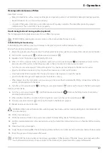
Page 53: ... 5 Foam marker blob interval Regulates the blob interval for the optional foam marker 6 Foam marker Left OFF Right Turns the optional foam marker on for each side Middle position is OFF 7 Section valves Turns single sections on or off Lever up is OFF and down is ON 8 Optional function A OFF B If extra equipment is added it can be controlled from here Middle position is OFF In order to close the en...

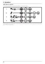
Page 54: ...n the following diagrams handle positions for different options are described ATTENTION When setting the handles in situation 4 for external filling the regulation valve also needs to be closed for the external filling to work properly 1 2 3 4 ...

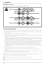
Page 55: ... courses ditches wells springs etc The washings from the cleaning area must not enter sewers Alternatively the washings can be retained in an appropriate receptacle diluted and distributed over a larger cultivated area see also Filling washing location requirements on page 44 4 Cleaning starts with the calibration as a well calibrated sprayer will ensure the minimal amount of remaining spray liqui...

Page 56: ...icals require the tank to be completely filled Add appropriate detergent and or deactivating agent e g washing soda or Triple ammonia Special detergents for sprayer cleaning is recommended as some also lubricate ball valves etc 7 Start the pump and operate all controls enabling the liquid to come into contact with all the components Leave the distribution valves until last Some detergents and deac...

Page 57: ...ozzles Close TurboFiller lid and squeeze the Chemical Container Cleaning grip to clean this device Open TurboFiller lid again and make sure that TurboFiller is empty When empty close the TurboFiller suction valve again Take care that the External fast filling connection and the line are not contaminated with chemicals 5 Turn the suction valve towards and the pressure valve towards and spray the li...

Page 58: ...pressure cleaner lubrication of the entire machine is recommended BoomFlush optional When having the BoomFlush ballofixes fitted to the end s of boom piping the cleaning procedure is 1 Follow the cleaning procedure to clean the sprayer the first two times 2 Open all BoomFlush ballofixes 3 Continue the cleaning procedure to clean the sprayer for the third time 4 Close BoomFlush ballofixes again WAR...

Page 59: ...n valve 2 The valve is spring loaded but can be kept open by pulling the string upwards in the V shaped slit 3 To release pull the string downward and the valve will close automatically If draining residues e g liquid fertilizer into a reservoir a snap coupler with hose can rapidly be connected to the drain valve and the liquid safely drained ...

Page 60: ...5 Operation 60 ...

Page 61: ... new grease becomes visible Pictograms in lubrication oiling plans designate the following 1 Lubricant to be used see Recommended lubricants 2 Recommended intervals hours μ ATTENTION If the sprayer is cleaned with a high pressure cleaner lubrication of the entire machine is recommended Recommended lubricants Boom lubrication oiling plan BALL BEARINGS Universal Lithium grease NLGI No 2 SHELL RETINA...

Page 62: ...6 Maintenance 62 Trailer lubrication oiling plan P T O lubrication oiling plan Serie 100 type P T O shaft C 50 ...

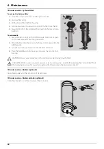
Page 63: ...onto filter end 5 Place the filter into housing with guide facing up 6 Ensure the O ring D on the hose fitting is in good condition and lubricated 7 Refit the suction hose B and steel clip A WARNING Always wear protective clothing and gloves before opening the filter 10 hours service In Line filter optional If the boom is equipped with In Line Filters unscrew the filter bowl to inspect and clean t...

Page 64: ...he filter onto the recess which may not be greased in the lid filter guide 3 Turn the two locks C inwards to lock the filter to the lid 4 Place the filter filter lid into housing and screw the lid until it hits the stop WARNING Always wear protective clothing and gloves before opening the filter DANGER Both the suction valve and pressure valve must always be closed before opening the Cyclone filte...

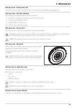
Page 65: ...ee the part Occasional maintenance Change of tyre WARNING If renewing tyres always use tyres with min load index as specified 50 hours service Wheel nuts Tighten wheel nuts as follows with following torque wrench settings Wheel hub to rim plate 490 Nm 362 lbft Tightening sequence See illustration and tighten in order of numbering μ ATTENTION When wheels has been mounted or re tightened the plastic...

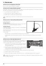
Page 66: ...it needs to be adjusted Correct length When the brake is relieved the cable must be tight and yet not stretched Lengthening shortening of the parking brake cable is carried out by adjusting the turnbuckle located inside the chassis 250 hours service Brake adjustment optional Lift the back of the sprayer from the ground It is recommended to use two lifting jacks placed underneath the axle Make sure...

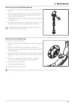
Page 67: ...onnected and pressure relieved 250 hours service Wheel bearings Check for play in the wheel bearings 1 Place stop wedges in front of and behind LH wheel and jack up RH wheel 2 Rock the RH wheel to discover possible play in the bearings 3 If any play support the wheel axle to prevent the trailer from falling down from the jack 4 Remove hub cap A and cotter pin B Turn the wheel and tighten the caste...

Page 68: ...cified torque first then to the full specified torque 15 Tighten again after 10 hours of work Check the torque every day until it is stabilised μ ATTENTION The shaft has a vertical and an horizontal cotter pin hole Use the one first aligned with the notch when loosening the castellated nut WARNING If you do not feel totally confident changing wheel bearings then contact your HARDI dealers workshop...

Page 69: ...linings and drums 13 Fit the shoe assembly with the anchor bolt H first Then pull the shoes away from each other and slide them over the cam afterwards Tighten the anchor bolt castle nut F again and fit a new cotter pin G 14 Check roller bearings for discolouration and wear renew if worn or damaged 15 Assemble drum D and bearings E using a new sealing ring J 16 Fill the hub and bearings with fresh...

Page 70: ...upper side inlets It has to be placed in the valve openings as shown All others are the type with black flap It is recommended to use new gaskets 3 when changing or checking the valves Diaphragms Remove the diaphragm cover 4 The diaphragm 5 may then be changed If fluids have reached the crankcase re grease the pump thoroughly Also check that the drain hole at the bottom of the pump is not blocked ...

Page 71: ...gm cover 4 The diaphragm 5 may then be changed If fluids have reached the crankcase re grease the pump thoroughly Also check that the drain hole at the bottom of the pump is not blocked Reassemble with the following torque setting Reassemble pump model 1303 with the following torque setting Cone check renewal for pressure regulation valve If it becomes difficult to build up sufficient pressure or ...

Page 72: ...he float should lie on the stop pin D of the rod and the O ring on the indicator should be positioned at the top position line A If any deviation is found do 1 Pull out the plug B 2 Loosen screws C 3 Adjust the length of the cord until it reads correctly 4 Push plug B back in place NOTE For best accuracy adjustment shall be done with the sprayer attached to the tractor normally used Level indicato...

Page 73: ...mbly can now be pulled out 4 Check cord and valve flap assembly C for wear replace seal D and assemble again 5 Assemble the valve assembly again using a new valve seat E Lubricate O rings F before assembly 6 Fit clip A again μ ATTENTION Check function of valve with clean water before filling chemicals into the tank Adjustment of 3 way valve The large ball valve s93 can be adjusted if it is too tig...

Page 74: ... little mechanical leverage may be used For RADIAL connections only tighten by hand Shield renewal on transmission shaft See the manufacturer s instruction book Replacement of transmission shaft cross journals See the manufacturer s instruction book Change of bulbs 1 Switch off the light 2 Loosen the screws on the lamp and remove the cover or lens 3 Remove the bulb 4 Fit a new bulb refit the cover...

Page 75: ...at 100 130 kPa inflate the tyre to a maximum of 250 kPa 36 p s i until they seat perfectly on the rim Never exceed the maximum mounting pressure moulded on the tyre After mounting tyres adjust inflation pressure to operation pressure recommended by the tyre manufacturer Do not use tubes in tubeless tyres DANGER Non observance of mounting instructions will result in the bad seating of the tyre on t...

Page 76: ...der the boom whilst adjustment is carried out Alignment of centre and inner wing sections 1 Unfold the boom and check alignment of the inner section with the centre section 2 If adjustment is necessary relieve pressure from the cylinder by folding the boom a few centimetres 3 Disconnect cylinder rod eye A from the inner section Note that some cylinder rods have a machined flat which can be used fo...

Page 77: ... only Please note that the rubber stop stop device A should be compressed 3 5 mm Therefore check that the distance between the tabs C is a little less than the length of the rubber stop itself The rubber stop may need to be spaced out with 1 or more flat washers in order to obtain correct compression Tighten nut to hold it in place Breakaway section adjustment The function of the breakaway section...

Page 78: ...ighten counternuts E again and remove weight WARNING Check boom alignment again If front cable was tightened the wing assembly will move a bit forward If front cable was loosened the wing assembly will move a bit rearward Therefore adjust fold cylinder if necessary as described in the section Alignment of centre section and inner wing sections Adjusting rear cable 1 Raise boom to its highest posit...

Page 79: ...m when pulled by hand NOTE Cables will be loose when the boom is unfolded 6 Tighten counternuts on the bolt assembly C again 7 Unfold the boom and inspect that the centre frame is correctly centred μ ATTENTION Adjust both boom wings in one sequence Adjust one cable a small amount at the time and then the other cable to equalize cable tension and maintain a level centre frame WARNING Never adjust t...

Page 80: ...procedure applies to both sides For SPB Z SPC Z models the following procedure is used 1 Ensure that cylinder is fully extended 2 Loosen counternut A 3 Apply an adjustable wrench to the machined surface at B 4 Turn the cylinder rod until boom is level to the ground 5 Secure counternut A again Same procedure applies to both sides Yaw damping Tighten loosen bolt A to adjust slack at point B μ ATTENT...

Page 81: ...ews A and pull out the pins B at one of the upper parallelogram arms and renew the wear bushes 4 Refit the arm 5 Repeat this on the other upper arm 6 The lower arms must be disconnected simultaneously 7 Grease all grease nipples 8 Remove the lifting gear again Shock absorbers If the shock absorbers loose their efficiency or start leaking oil they should be replaced Shield renewal on transmission s...

Page 82: ...n valves so that the anti freeze is sprayed through the nozzles as well The anti freeze will also prevent O rings seals diaphragms etc from drying out On sprayers with FlexCapacity pump this must also be engaged and flushed 6 Lubricate all lubricating points according to the lubricating scheme regardless of intervals stated 7 When the sprayer is dry remove rust from scratches or damage in the pain...

Page 83: ...ressure gauges again Seal with Teflon tape 5 Connect the sprayer to the tractor including hydraulics and electrics 6 Check all hydraulic and electric functions 7 Empty the tank for remaining anti freeze 8 Rinse the entire liquid circuit of the sprayer with clean water 9 Fill with clean water and check all functions 10 Check function of brakes Please note that brake power will be reduced until the ...

Page 84: ...6 Maintenance 84 ...

Page 85: ...lves from closing correctly thus reducing the pump flow 6 A bad reassembly of the pump elements especially the diaphragm covers causes air intakes or leaks and reduces the pump flow 7 Rusted or dirty hydraulic components cause bad connections and early wears 8 A badly charged or faulty battery causes failures and misbehaviour in the electrical system Therefore ALWAYS check 1 Suction and pressure f...

Page 86: ... to clog Clean all filters Formation of foam Air is being sucked into system Check tightness gaskets O rings of all fittings on suction side Excessive liquid agitation Reduce pump r p m Check safety valve is tight Ensure returns inside tank are present Use foam damping additive Liquid leaks from bottom of pump Damaged diaphragm Replace See changing of valves and diaphragms Vibrations in system and...

Page 87: ... systems Bypass valve does not close properly Check close screw in by pass valve Internal leaks in flow regulator Replace flow regulator O rings and backup rings Replace flow regulator Individual ram does not move Clogged restrictor Dismantle and clean restrictor FAULT PROBABLE CAUSE CONTROL REMEDY Boom slow eradic Air in system Loosen ram connection and activate hydraulics until oil flow has no a...

Page 88: ...CONTROL REMEDY Boom will not fold in or out Cylinder Adjust the fold cylinder Boom will not fold completely Cables Check adjustment of centre cables Boom not aligned Cables Adjust and grease complete boom cables and stops Boom will not stay in spraying position Various Check for hydraulic leaks through solenoid block Check for a solenoid that is stuck open Wing to be kept folded swings out when un...

Page 89: ...ith TurboFiller and Hydraulic brakes Full tank weights are with full main tank 2500 litre water and full rinsing tank 260 litre water All weights in Kilograms kg Sprayer A Total length mm B Total width mm C Total height mm 2200 SPB 5 40 2 98 2 90 2200 PRO 5 60 2 55 3 32 Axle load Drawbar load Total weight Unfolded empty 1497 57 1554 Folded empty 1385 169 1554 Unfolded full 3580 849 4429 Folded ful...

Page 90: ... Main tank capacity 2500 Litres Rinsing tank capacity 260 Litres Clean water tank capacity 20 Litres Foam marker tank capacity 38 57 or 76 Litres Mesh Filter gauze width EasyClean Cyclone In line Nozzle 30 0 58 mm Yes 50 0 30 mm Yes standard Yes Yes 80 0 18 mm Yes Yes standard Yes Yes 100 0 15 mm Yes Yes Tyre size Recommended inflation pressure Min load index A2 A8 270 95R38 11 2 R38 2 4 bar 35 p ...

Page 91: ...ting pressure Operating temperature range 2 to 40 C 36 F to 104 F Operating pressure for safety valve 15 bar 220 psi Max pressure on the pressure manifold 20 bar 290 psi Max pressure on the suction manifold 7 bar 100 psi Max operating temperature 75º C 167ºF Tractor 210 bar 3046 psi min 160 bar 2321 psi ...

Page 92: ...nk hose and synthetic fittings can be incinerated at an authorized disposal plant The metallic parts can be scrapped Always follow local legislation regarding disposal Materials used Tanks HDPE Frame etc Steel Pump Cast iron Diaphragms PUR Hoses suction PVC Hoses pressure EPDM Valves Glass reinforced PA Filters PP Nozzles Unfilled POM Fittings Glass reinforced PA ...

Page 93: ...RAY II 1a 5 S1 1b 6 S1 1c 26 End nozzle L 2a 7 S2 2b 8 S2 2c 25 End nozzle R 3a 9 S3 3b 10 S3 3c 29 12V sensor 4a 11 S4 4b 12 34 4c 4 PWM 1TX 5a 14 S5 5b 15 S5 5c 27 GND 6a 16 S6 6b 17 S6 6c 13 Optional 5 Reg feedback 7a 18 S7 7b 19 S7 7c 33 Option 1 4 20mA 8a 37 S8 8b 36 S8 8c 32 Option 2 Frq 9a 35 S9 Air angle 0 5V 9b 34 S9 Fan speed 0 5V 9c not connected Option 3 Tank gauge 10a 21 On off 10b 22...

Page 94: ...sensor Brown Blue Option 2 RPM sensor Brown Blue Black Speed Brown Blue Black Flow Brown Blue Black Left end nozzle Pendulum lock at HAY LPY Brown Blue Right end nozzle Pendulum lock at HAY LPY Brown Blue Regulation Yellow Brown Blue Bypass EC on off Brown Blue Section 9 x x Section 8 User defined A B x x Section 7 Brown White Section 6 Yellow Grey Section 5 Brown Blue Section 4 Brown Blue Section...

Page 95: ...8 Technical specifications 95 Charts Boom hydraulic Z Boom hydraulic Y ...

Page 96: ...8 Technical specifications 96 ...

Page 97: ...Filling Device valve 18 F Filling chemicals through tank lid 47 Filling liquid chemicals by HARDI TurboFiller 48 Filling of water 44 Filling powder chemicals by HARDI TurboFiller 50 Filling through tank lid 45 Filling washing location 44 Filters 19 Frame 13 G General info 85 89 H HARDI MATIC 19 HARDI MATIC 19 Hose reel 25 Hydraulic system 87 I Identification plates 16 In field diluting 57 In Line ...

Page 98: ...yer use 13 Spraying circuit 63 Step 24 Storage 82 Suction filter 19 63 85 Suction valve 18 Support leg 27 Symbols 9 T Tank 13 Tank level indicator 25 Tanks 13 Technical residue 58 Temperature and pressure ranges 91 Transmission shaft 29 TurboDeflector valve 21 TurboFiller 21 TurboFiller rinsing 52 TurboFiller suction valve 21 U Unloading the sprayer 27 V Valves 17 Valves and symbols 17 View 14 W W...

Page 99: ...Spare parts To see updated spare part information the website www agroparts com can be visited Here all parts information can be accessed when free registration has been made ...

Page 100: ...HARDI INTERNATIONAL A S Helgeshøj Allé 38 DK 2630 Taastrup DENMARK ...

Reviews: