background image

2 - General Safety Instructions

12

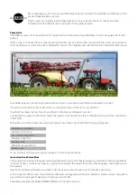
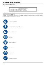
Organizational Measures

Personal Protective Equipment

The operator must use the necessary personal protective equipment as per the information provided by the manufacturer 
of the plant protection product to be used, such as:

 This Instruction Book

must always be kept together with the sprayer

must always be easily accessible for the operator

Chemical-resistant gloves

Chemical-resistant and disposable overalls

Water-resistant footwear

Face shield

Breathing protection

Eye protection

Head protection

Skin protection products

Summary of Contents for RANGER PRO VH

Page 1: ...RANGER PRO VH Original Instruction book 67009400 110 version 1 10 GB 09 2016 www hardi international com ...

Page 2: ... in the directive 2006 42 EC article 2 Connecting the sprayer to the tractor makes the operator responsible for safety and health when using that combination of machines Before first use of the sprayer the owner and operator must take note of all of the following obligations For more details on these tasks please see page 7 in this Instruction Book Instruction Book Formalities The original Instruc...

Page 3: ...2006 42 EC regarding the Machinery Directive CE marking 2009 127 EC and later amendments regarding machinery for pesticide application 2014 30 EU regarding electromagnetic compatibility EMC as well as the following ISO standard ISO 14982 regarding test methods and acceptance criteria for electromagnetic compatibility for agricultural machinery Electronic components on the machine are tested and in...

Page 4: ...1 EU Declaration 4 ...

Page 5: ...ining 19 Authorized Persons 19 Safety Measures in Normal Operation 20 Protection Equipment 20 Residual Energy 21 Possible Dangers 21 Service and Maintenance Work 22 Statutory Inspection 22 Preventive Measures 22 Design Changes 23 Operator Limitations 23 Spare Parts Wear Parts and Aids 23 Cleaning and Disposal 24 Environmental Protection 24 Workstation 25 Intended Place for Operator 25 Risks of Non...

Page 6: ...ozzle Pressure Gauge 55 SelfSteer 55 Drawbars 56 Tank Level Indicator 56 External Cleaning Device 56 4 Sprayer Setup General Info 57 Unloading the Sprayer from the Truck 57 Before Putting the Sprayer into Operation 57 Jack Up the Sprayer 57 Support Leg 58 Transmission Shaft 59 Operator Safety 59 PTO Installation 59 Mechanical Connections 60 Hose Package Support 60 Drawbars 60 Hydraulic Systems 61 ...

Page 7: ... Location Requirements 81 Parking the Sprayer 81 Before Returning to Refill the Sprayer 81 Filling of Water 82 Filling Through Tank Lid 82 External Filling Device 83 Filling of Rinsing Tank 83 Filling of Clean Water Tank 84 Safety Precautions Crop Protection Chemicals 84 Filling Chemicals Through Tank Lid 85 Filling Liquid Chemicals by using HARDI TurboFiller 86 Filling Powder Chemicals by using H...

Page 8: ...e Check Adjust Drawbar 116 250 Hours Service Hydraulic Circuit 116 250 Hours Service Hoses and Tubes 116 250 Hours Service Wheel Bearings 116 250 Hours Service Inspect Parking Brake 117 250 Hours Service Brake Adjustment 117 250 Hours Service Hydraulic Brakes 117 250 hours service Air brake filters 118 1000 Hours Service Wheel Bearings and Brakes 119 Occasional Maintenance 121 Lifting and Removing...

Page 9: ...hnical Specifications Dimensions 143 General Info 143 Overall Dimensions 143 Wheel and Axle Dimensions 143 Weight 144 Pump Specifications 145 Pump Model 364 5 5 145 Pump Model 364 7 0 145 Pump Model 364 10 0 145 Other Specifications 146 Tractor Requirements 146 Temperature and Pressure Ranges 147 Brakes 147 Filters 148 Technical Residue 148 Airborne Noise Emission 148 Tyre Pressure 149 Materials a...

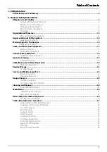
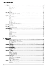
Page 10: ...Table of Contents 6 ...

Page 11: ...reading it please contact the manufacturer or your HARDI dealer A worker is hereinafter called an operator An operator is a person who installs operates configures adjusts maintains cleans repairs transports or moves the sprayer Use of Work Equipment Throughout the lifetime of the sprayer the owner shall take every measure to ensure the safety of the sprayer and its equipment made available to ope...

Page 12: ...pment has been installed correctly and is operating properly 2 In order to ensure that health and safety conditions are maintained and that deterioration liable to result in dangerous situations can be detected and remedied in good time the employer shall ensure that work equipment exposed to conditions causing such deterioration is subject to 3 The results of inspections shall be recorded and kep...

Page 13: ...g them inasmuch as they affect work equipment situated in their immediate work area or site even if they do not use such equipment directly 3 The information and the written instructions shall be comprehensible to the workers concerned Article 9 Training of workers Without prejudice to Article 12 of Directive 89 391 EEC the employer shall take the measures necessary to ensure that a the use of wor...

Page 14: ...cial by authorized persons The results of inspection testing shall be recorded and kept Health Issues Ergonomics and occupational health aspects shall be taken fully into account by the owner Obligationsof the Operator Before starting work the operator or anyone incharge of working with on the sprayer is obliged to comply with the basic workplace safety instructions and accident prevention regulat...

Page 15: ...following causes Improper use of the sprayer Improper installation commissioning operation and maintenance of the sprayer Operation of the sprayer with defective safety equipment or improperly attached or non functioningsafety equipment Non compliance with the instructions in the instruction manual regarding commissioning operation and maintenance Unauthorized design changes to the sprayer Insuffi...

Page 16: ...provided by the manufacturer of the plant protection product to be used such as This Instruction Book must always be kept together with the sprayer must always be easily accessible for the operator Chemical resistantgloves Chemical resistant and disposable overalls Water resistantfootwear Face shield Breathing protection Eye protection Head protection Skin protection products ...

Page 17: ...r serious physical injury if the instruction is not followed This symbol means WARNING Be alert as your safety can be involved The WARNING symbol indicates a medium risk for immediate death or serious injury if the instruction is not followed μ This symbol means ATTENTION This indicates an obligation to special behaviour or an activity required for proper sprayerhandling Thisinstructionwillhelp yo...

Page 18: ...n the machine Operators or anyone in close range of the sprayer must respect these warnings The labels should always be clean and readable Worn or damaged labels must be replaced with new ones Contact your HARDI dealer for new labels Note that not all labels shown hereafter will apply to your sprayer this depends on the sprayer model which labels apply ...

Page 19: ...ing Service Turn off the engine and remove ignition key before performing maintenance or repair Service Tightentothetorqueaccordingtoinstruction book Risk of death Do not attempt to enter tank Risk of burn Stay clear of hot surfaces Risk of injury Do not open or remove safety shields while engine is running Risk of injury Flying objects keep a safe distance from the machine as long as the engine i...

Page 20: ...Risk of falling off Do not ride on platform or ladder Risk of sprayer tipping over Be aware when disconnecting the sprayer Grapping area Manual handling of the boom etc Not for drinking This water must never be used for drinking Not for drinking This water must never be used for drinking Lifting point Lifting point Load index Max permitted load rating is 164 at 40 km h or 5000 kg EasyClean filter ...

Page 21: ...yer is started up all the safety and protection equipment must be properly attached and fully functional Check all safety and protection equipment regularly Repair or replace the equipment as needed Faulty Safety Equipment Faulty or disassembled safety and protection equipment can lead to dangerous situations ...

Page 22: ... The applicable workplace safety Follow these regulations especially when driving on public roads and routes Comply with the appropriate statutory road traffic regulations These vary from country to country and there may be local regulations which need to be followed local law demands that the operator is certified to use spray equipment using pesticides or liquid fertilizer Make sure you understa...

Page 23: ...al training shall be considered as a specialist Due to their specialist training and their knowledge of the appropriate regulations they can evaluate the work with which they have been appointed to and detect possible dangers Examples of these persons are sprayer importers dealers and service engineers and service technicians Comment A qualification equivalent to specialist training can be obtaine...

Page 24: ...s in Normal Operation Protection Equipment Only operate the sprayer if all the safety and protection equipment is fully functional Check the sprayer at least once a day for visible damage and check the function of the safety and protection equipment ...

Page 25: ...ppening due to residual energy Below are some examples on where the sprayer s residual energies may be present Mechanical Energy springs under tension weights exposed to gravity heat from brake drums Hydraulic Energy trapped oil under pressure in cylinders hoses and accumulators heat from cylinders and oil tank Pneumatic Energy air tank air activated brake system pressure dampers for fluid system ...

Page 26: ...ractor s hydraulic levers in neutral position to relieve oil pressure turn off the tractor and remove the ignition key dismount the hydraulic hoses connected from the tractor to the sprayer Electric system turn off the tractor and remove the ignition key dismount the electric cables from the tractor s battery Fluid system turn off the tractor and remove the ignition key Compressed air turn off the...

Page 27: ... the state specified by the approval It is strictly forbidden to Drill holes in the steel frame or in the running gear Increasethe size of existing holes in the steel frameor inthe runninggear Weld support parts Risk of crushing cutting catching squeezing getting trapped being drawn in or being struck by sprayer parts due to the failure of support parts Spare Parts Wear Parts and Aids Immediatelyr...

Page 28: ... and Disposal Environmental Protection Carefully handle and dispose of any materials used in particular When carrying out work on oiled or lubricated sprayer parts When cleaning using solvents Always follow local legislation regarding disposal ...

Page 29: ...rferes with the operator or if the operator is trying to operate the sprayer from other places than the tractor s driver seat this can result in negligent or incorrect handling of the vehicle Risk of the operator loosing his concentration and focus on operating the vehicle correctly Risk of the operator loosing his ability to operate the vehicle correctly Risk of fatal accidents while driving Risk...

Page 30: ... to people to the environment and to the sprayer Danger to people through non secured working areas Danger to people through mechanical and chemical influences Failure of important sprayer functions Failure of prescribed methods of maintenance and repair Leakage of hydraulic fluidor spray fluid to the environment Can lead to the loss of all warranty claims ...

Page 31: ... can see clearly Drive in such a waythat you always have fullcontrol over the tractor with the attachedsprayer In doing so take your personal abilitiesinto account as wellas the road traffic visibility weatherconditions andthe driving characteristicsof the tractorand of the connected sprayer Slow down when driving in uneven terrain or when making sharp turns as the sprayer might be in risk of turn...

Page 32: ...he sprayer Any helpers may only act as guides standing next to the vehicles and helpers may only move between the vehicles when both are at a standstill Beforeconnectingthesprayertoor disconnectingthesprayer fromthetractor sthree pointlinkage securetheoperatingleverof the tractor hydraulicsystem so that unintentionalraising or lowering is prevented When coupling and uncoupling sprayers move the su...

Page 33: ...a partially filled tank It is forbidden to stand in or near the working area of the sprayer climb the sprayer stand or sit on the sprayer stand in the turning and swivel range of the sprayer There are crushing and cutting points at externally actuated sprayer points e g hydraulic cylinders Only actuate externally actuatedsprayer parts when you are sure that no one is standing within the prescribed...

Page 34: ...our driving speed to the prevailing conditions Before driving downhill switch to a low gear When making turns lower your speed Checking the Vehicle Before transporting the sprayer on a road complete the following check points for the tractor and sprayer 1 Spray boom is folded and resting in transport brackets with the intended locks engaged 2 Engage transport locks on the steering cylinders 3 Supp...

Page 35: ...the loaded vehicle combination tractor plus connected sprayer Before driving off always switch off independent wheel braking on the tractor lock the pedals Whenturningcornerswiththesprayerconnected takethe broadloadandbalanceweightof thesprayerinto account Slow down as needed to avoid tilting or overturning of the vehicle especially on sloping roads Hydraulic System The hydraulic system is operati...

Page 36: ...the tractor s battery When disconnecting the battery disconnect the negative terminal first followed by the positive terminal When connecting the battery connect the positive terminal first followed by the negative terminal Always place the appropriate cover over the positive battery terminal If there is accidental earth contact there is a risk of explosion If climbing onto the sprayer during serv...

Page 37: ...Before switching on the universal joint shaft check that the selected universaljoint shaft speed rpm of the tractor matches the permitted drive speed of the sprayer Stay below the maximum speed rpm suitable for the PTO shaft Instruct people to leave the danger area of the sprayer before you switch on the universal joint shaft While work is being carried out on the universal joint shaft there must ...

Page 38: ... of contamination Only fill the sprayer using a free flow of water from the mains water supply or from an external water tank Environmental Precautions It is essential to reduce the environmental impact of plant protection chemicals to a minimum Particularly the soil subsoil water streams lakes flora and fauna must be in focus Contamination of subsoil water must be prevented by paying particular a...

Page 39: ...prayer to prevent unintentional movements of the sprayer Switch off the PTO Switch off the tractor and remove the ignition key to prevent unintentional starting Activate the parking brake to prevent rolling Put chocks in front of and behind the wheels to prevent rolling Electric power must be disconnected from the sprayer Any service work on electronic electric parts must be carried out under dry ...

Page 40: ...seating and retighten them as necessary If electrical welding is used on the tractor and on the attached sprayer disconnect the cable to the tractor s generator and battery before carrying out electrical welding work on the tractor and on the connected sprayer Remove all inflammable or explosive materials from the area to prevent fire Pressure test the spray functions with clean water prior to fil...

Page 41: ...auge 4 SafetyLocker 5 Support leg 6 Pump 7 Hitch 8 Step 9 Suction filter 10 Suction valve 11 Valve for external filling device 12 Agitation valve 13 Pressure valve 14 Cyclone filter 15 TurboFiller valves 16 TurboFiller 17 Lid for RinseTank 18 Handle for drain valve 19 Lid for clean water tank ...

Page 42: ...3 Description 38 20 Distribution valves 21 Main tank 22 Hose reel and spray gun 23 Handbrake 24 Air brakes tank 25 RinseTank ...

Page 43: ...xxxxxxxxxxx xxxxx xxxxx xxxxx xxxxxxxxx xxxxx xxxxxxxxx xxxx xxxx xxxxx Herthadalvej 10 4840 Nørre Alslev Denmark Fabriqué en France 97830000 kg kg kg kg kg kg HARDI EVRARD S A S 62990 Beaurainville France www hardi fr com N d identification Masses maximales admissibles Attelage Essieu 1 Essieu 2 Essieu 3 PTAC PV PTRA Marque TVV Année fabrication Modèle Capacité Litres Rampe Réceptionné le par la ...

Page 44: ...3 Description 40 Data On the next page you will find descriptions of the data on the ID plate 1 2 3 4 5 6 7 8 19 9 10 11 12 13 14 15 16 17 18 Herthadalvej 10 4840 Nørre Alslev Denmark ...

Page 45: ...ed In special cases GCWR PTRA Reserved for future use Sum of gross vehicle masses of towing vehicle and trailer USA Gross Combination Weight Rating GCWR France Poids Total Roulant Autorisé PTRA 8 Not used In special cases Drawbar category Reserved for future use Minimum required drawbar category to tow the trailer Horsepower HP dependent CAT I 20 45 HP CAT II 40 100 HP CAT III 80 275 HP CAT IV 180...

Page 46: ...are made of impact proof polyethylene resistant to UV radiation and chemicals The main tank has a purposeful design with no sharp corners for easy cleaning The filling hole is placed so it can be accessed from the platform This ensures an easy access for the filling of chemicals cleaning of the tank etc The sprayer may also be equipped with a rinsing tank and a clean water tank A large easy to rea...

Page 47: ... the side of the footboard μ ATTENTION Although this canister is meant for the storing of non contaminated items it must never be used for the storing of food beverage or other items meant for human consumption Safety Locker A safety locker can be mounted on the platform railing The safety locker is for storage of safety gear such as non contaminated protective gear soap for hand washing etc The l...

Page 48: ...d from the pump will be routed to The active function is indicated The handle is turned so that the indicator points to the label for required function If the handle is turned to a position without a label unused function the valve is closed B Agitation valve With the adjustable agitation valve it is possible to combine spraying with a high volume rate at high pressure with agitation at the same t...

Page 49: ...ivating the valve starts stops the filling process Note that the suction valve must be closed for maximum filling capacity D Suction valve This valve is to select from where the pump sucks the liquid The handle is turned until it is pointing at the label for the required function If the handle is turned to a vertical position indicator is not pointing at a label the valve is closed Suction from ex...

Page 50: ...with a red hose tail A Cyclone pressure filter is fitted to the sprayers left side just behind the manifold valves It has a built in self cleaning function In line pressure filters can be fitted at each boom section as an option Nozzle filters are fitted at each nozzle μ ATTENTION All filters should always be in use and their function should be checked regularly Pay attention to the correct combin...

Page 51: ...s going to be clogged when spraying This position is used when rinsing the boom if the main tank is empty C This position marked with 3 dots Flushing position which is used if filter is clogged Lift and hold the lever to use this position which largely increases return flow and flushes the filter The top green pressure valve must be set to Spraying μ ATTENTION Use of position C is no guarantee for...

Page 52: ...lly closed Openthe valve when chemicals are to be filled into theTurboFiller and transferred to main tank TurboDeflector Valve This TurboDeflector valve activates the vortex flushing of theTurboFiller Lift the lever to lock it in open position for continuous liquid rotation in the hopper Chemical Container Rinsing The upper lever is used for two purposes When the TurboFiller lid is open For rinsin...

Page 53: ...Water Tank A clean water tank is integrated into the left side cover It is accessed for filling at the sprayer s left side when entering the platform The ball valve for water draining is located on the sprayer s left side The water in this tank is for hand washing for cleaning of clogged nozzles etc Only fill this tank with clean water from the tap Capacity approximately 20 litres WARNING Although...

Page 54: ... One Way Valve Safety Valve Pressure Inlet for Main Tank Rinsing Nozzles RinseTank 21 22 23 24 27 28 30 33 40 41 43 45 46 47 48 53 RinseTank Filling Coupler Valve block for TurboFiller TurboFiller Ejector for TurboFiller Filling Coupler Filling Valve Filler Hose to Tank Inlet Spray Gun Dilution Valve for Suction Dilution Valve for Rinsing Flowmeter Boost Valve Pressure Regulation Drain Valve for M...

Page 55: ...draulic Blocks Hydraulic blocks fitted to the sprayer are described below Spray Boom The main hydraulic block which manages hydraulic pressure for the boom controls ParaLift This hydraulic block manages hydraulic pressure for the ParaLift ...

Page 56: ...tre hydraulics block is necessary if the tractor uses open centre hydraulicsand or load sensing For adjustment see Open Centre Hydraulics on page 62 If in doubt what your tractor is using see the tractor s instruction book or ask your tractor dealer O LS ...

Page 57: ... it protects the boom against vibrations and shocks when driving on uneven ground This ensures longer boom life and improves boom stability for better spray distribution Booms are available in 12 15 16 and 18 m working width All booms are provided with spring loaded breakaway For 3 folded booms the terminology is as follows A Centre section B Inner section C Middle section D Outer section E Breaka...

Page 58: ... the sprayer frame for easy access to the platform Support Leg This support leg supports the sprayer at the front when it is not coupled to a tractor When coupling the sprayer to a tractor the support leg can be raised or lowered to adjust the sprayer to fit the tractor s hitch point Illustration of the support leg when standing on the ground The support leg is close to vertical when standing ...

Page 59: ...The SelfSteer will make the sprayer turn a little later when the tractor begins turning at the headland compared to a conventional hitch This gives you a smaller turning radius resulting in shorter headlands a better tracking on headlands Furthermore the SelfSteer can include SlopeCorrection which has the same function as the normal SelfSteer but can also be used for track correction on slopes thi...

Page 60: ...ning the complete sprayer externally in the field with clean water using a spray gun The External Cleaning Device is located on the boom centre section at the back DANGER The cleaning device produces a water jet with high pressure Incorrect use may result in injuries When using the cleaning device follow these rules Wear personal protective equipment on your body feet hands and head Particles and ...

Page 61: ...chemicals and fertilizers discolouring the enamel If this is done before the sprayer is put into operation for the first time it will always be easy to clean the sprayer and keep the enamel clean for many years This treatment should be carried out every time the protection film is washed off Jack Up the Sprayer When the sprayer needs wheel mounting or changing of wheels wheel bearings or brakes ja...

Page 62: ...n the support leg 2 Place the lock pin into the horizontal locking hole 3 Turn handle to lower the support leg to the ground 4 When thesupportleg fullysupports thesprayer thesprayercan be detached from the tractor With SelfSteer The drawbar has a retractable support leg which is stored in hoisted position to minimise crop damage How to place sprayer on the support leg 1 Use tractor lift to lift th...

Page 63: ...er Also NEVER cross over a rotating PTO shaft to reach the other side of the sprayer 7 Prevent protection guards from rotating by attaching the chains allowing sufficient slack for turns 8 Make sure that protection guards around the tractor PTO and the implement shaft are intact DANGER A ROTATING TRANSMISSION SHAFT WITHOUT PROTECTION GUARDS IS FATAL PTO Installation First installation of the trans...

Page 64: ...cables are long enough in tight turns when fully steered Drawbars A low hitch drawbar can be delivered with different coupling parts The drawbar can be configured as a fixed or a SelfSteer model Furthermore the SelfSteer may be equipped with SlopeCorrection All drawbars are fastened to the underside of the sprayer near the rear axle with 6 bolts secured by lock nuts Furthermore the drawbar is supp...

Page 65: ...double acting outlet for hydraulic slanting control VHY option VHZ model One double acting outlet for the electro hydraulic operation of the boom functions SelfSteer models with SlopeCorrection also require One double acting outlet for the control of SlopeCorrection The hydraulic hoses are marked with arrows to indicate the direction of oil flow The hydraulic system requires an oil flow between 25...

Page 66: ... with this restrictor installed WARNING If the reaction time seems too long before the hydraulic function is enabled replace the restrictor with the bigger model from the kit to allow more oil flow to pass through Ask your HARDI dealer for correct setup and correct connection if in doubt WARNING Before operating the hydraulics the valve should be set according to the specific tractor model If you ...

Page 67: ...lug The unit requires Wire 2 5 mm2 Fuse 10 amps Hydraulic control unit requires Wire 4 0 mm2 Fuse 16 amps JobCom connector 3 pin plug The unit requires Wire 6 0 mm2 Fuse 25 amps Traffic light connector 7 pin plug The unit requires Wire 6x 1 5 mm2 1x 2 5 mm2 The cable is custom made and must not be changed to another type Tractor must follow ISO 1724 ISOBUS connector 9 pin plug The unit requires Wi...

Page 68: ...bent and shortened A spacer C is also supplied to allow further attachment possibilities Find the best solution for your tractor or vehicle Tube B plate is staggered so that if correctly orientated all boxes will line up μ ATTENTION See also the controllers instruction book for further details of fitting the controller equipment Road Safety Kit Connect the plug for rear lights to the tractor s 7 p...

Page 69: ...ddle of the gaps in vertical direction Distance from centre of the sensor to top of the brake drum xxx mm brake drum 60 mm xxx mm brake drum 75 mm NOTE If necessary readjust the bracket C for the sensor 3 Adjust air gap B to 3 6 mm Use a feeler gauge or similar tool μ ATTENTION Adjustment of the air gap shall be made from adjusting the carriage bolts for the speed ring 4 After adjustment spin up t...

Page 70: ...e PTO and thereby the number of revolutions of the pump corresponding to the intended travelling speed Remember to keep the number of revolutions of the PTO between 300 600 rpm pump 540 rpm or 650 1100 rpm pump 1000 rpm 6 Push up the pressure regulation switch at the spray control unit until the required spray pressure is shown on the pressure gauge Adjustment of pressure equalization 7 Close the ...

Page 71: ... condition of O rings and lubricate if necessary or replace them if damaged before reassembly DANGER Never open the Cyclone filter unless the top green pressure manifold valve and bottom black suction manifold valve are both closed turned to the unused position Otherwise spraying liquid may hit you when opening the filter and thereby draining the main tank ...

Page 72: ...andbrake is installed loosen the pointed screw on the brake operating arm 16 Extend or retract the axle A sack barrow and a rod will facilitate the operation 17 Tighten the clamp bolts A with a torque of 250 Nm Lower the wheel to the ground 18 Repeat the procedure on the right wheel 19 Check if the distance from centre tyre to centre of rear frame is equal at the right and left side 20 Retighten b...

Page 73: ...ke hubs Track width mm X dimension mm Rim mounting position Track width mm X dimension mm Rim mounting position 1520 835 A 1500 825 A 1570 860 A 1550 850 A 1620 885 A 1600 875 A 1642 735 B 1650 900 A 1670 910 A 1700 925 A 1692 760 B 1750 950 A 1720 935 A 1800 975 A 1742 785 B 1822 825 B 1770 960 A 1850 1000 A 1792 810 B 1872 850 B 1820 985 A 1900 1025 A 1842 835 B 1922 875 B 1870 1010 A 1950 1050 ...

Page 74: ... at 12 o clock 2 Remove the valve body and fill liquid until it reaches the valve 3 When surplus liquid is drained through the valve stem fit the valve body again 4 Adjust tyre pressure and lower the wheel Please refer to Tyre Pressure on page 162 DANGER It is very important that the CaCl2 is added to the water and agitated until it is fully dissolved Never pour water on to CaCl2 If you get CaCl2 ...

Page 75: ...ontainer 3 To empty the tyre completely the tyre is inflated and a thin drain tube is led to the bottom of the tyre The air pressure will now empty the remaining liquid 4 Remove the drain tube fit the valve and inflate the tyre to specified pressure See Technical Specifications in the table Tyre pressure μ ATTENTION Disposal of CaCl2 has to take place according to local legislation ...

Page 76: ...arking brake before the rope breaks μ ATTENTION To ensure safe engagement and to avoid damages to the parking brake use a rope with an ultimate stress between 690 and 785 N WARNING Release the parking brake before driving Hydraulically Activated Brakes This requires aspecial trailer brakevalve attached to the tractor hydraulic and brake system Connect the snap coupler to the tractor brake outlet W...

Page 77: ... obtaining optimal air pressure to the trailer brakes WARNING Driving with a wrong setting for the load apportioning valve will result in excessive or insufficient braking which can cause hazardous situations Manual Control of Air Brakes The braking system can be controlled manually to move the trailer when it is not coupled to the tractor Near the platform at the front of the trailer a black and ...

Page 78: ...e circuit for leaks Dual Line Air Brakes 1 Flip the snap coupler protection flaps away 2 Connect the two snap couplers for supply and control to the tractor outlets red and yellow The couplers are colour coded and secured against incorrect attachment 3 Let the air compressor fill the sprayer s air reservoir 4 Check brake circuits for leaks Coupling color Pneumatic circuit on the sprayer Red closin...

Page 79: ... than the ones described in this instruction book a new risk assessment and a workplace assessment must be completed for this use This obligation lies with the owner and operator according to EU directive 2009 104 EC see page 7 Improper use of the sprayer results in risks to your safety health and even a risk of death If no local law demands that the operator must be certified to use spray equipme...

Page 80: ...main tank Black Blue 97816100 Suction from RinseTank Black Blue 97816200 Filling of main tank from external tank Black Blue 97816300 Filling of main tank Black Green 97816500 Spraying Pressurized nozzles Black Green 97816600 Cleaning of main tank inside Black Green 97816700 Agitation in main tank Black Green 97817100 External cleaning Black Green 97817200 Filling of RinseTank Black Green 97817000 ...

Page 81: ... unfolding functions in areas with overhead power lines Unintended boom movements may cause contact with overhead power lines causing a risk of fatal accidents μ ATTENTION A label HARDI item no 978448 follows the sprayer This label must be placed in the cabin visible from the operator s seat Single Sided Unfolding 1 Activate hydraulic control lever 2 Raise the boom half way to the top as minimum 3...

Page 82: ...ractor s hydraulic levers Following operations are carried out by the tractor s hydraulic control levers Raising lowering of the boom Folding unfolding of the boom Slanting control optional equipment μ ATTENTION Only unfold and fold the boom when the tractor and sprayer are parked on level ground ...

Page 83: ...itches 3 and 5 downwards to lower individual tilt rams 3 Push switch 7 and 8 outwards to unfold the boom 4 Push switch 4 downwards to lower the boom to correct working height above the crop or ground level 5 Push switch 2 to the right to unlock the trapeze μ ATTENTION If the boom is not symmetrically unfolded e g when using alternative boom widths the trapeze must be locked during driving Failure ...

Page 84: ... the Spray Technique book for instructions on the use of filters nozzles etc and their combination in use with specific spraying applications Quick Reference Operation In the following diagram the handle positions for different options are described 1 2 3 4 5 ...

Page 85: ...g is to take place If so choose a different location for each refilling If no other requirements of distances exist the filling should not take place closer than 1 300 metres from public or non public water supplies for drinking purposes and 2 50 metres from surface water watercourses lakes and coastal waters treatment sumps cesspools of drainage systems and nature reserves μ ATTENTION Legislation...

Page 86: ...l water through the strainer basket to prevent foreign particles from entering the tank An overhead tank can be used in order to obtain high filling capacity WARNING Do not let the filling hose enter the tank Keep it outside the tank pointing towards the filling hole If the hose is led into the tank and the water pressure drops at the water supply plant chemicals may be sucked back and contaminate...

Page 87: ... is running and the filling hose is connected If this valve is opened without the pump running liquid will stream out of the coupler WARNING Do not leave the sprayer while filling the tank and keep an eye on the level indicator in order NOT to overfill the tank μ ATTENTION Observe local legislation regarding use of filling device In some areas it is prohibited to fill from open water reservoirs la...

Page 88: ...ety Precautions Crop Protection Chemicals Always be careful when working with crop protection chemicals WARNING Always wear proper protective clothing before handling chemicals Personal protection Depending on chemical type protective gear equipment should be worn to avoid contact with the chemicals such as Gloves Waterproof boots Headgear Respirator Safety goggles Coverall with chemical resistanc...

Page 89: ...e closed or turned to unused function 3 Engage the pump and set PTO revolutions to 540 rpm 4 Add the chemicals through the main tank hole 5 Keep PTO engaged so that the spray liquid is continuously agitated until it has been sprayed on the crop DANGER Before turning Pressure SmartValve past Pressure draining TurboFiller it is very important to ensure that the quick coupler lid is correctly and com...

Page 90: ...ely emptied there is a risk of chemicals being sucked out of the main tank 6 If the chemical container is empty it can be rinsed by the Chemical Container Cleaning device Place the container over the multi hole nozzle and push the container for cleaning DANGER In order to avoid spray liquid hitting the operator do not press the lever unless the multi hole nozzle is covered by a container as spray ...

Page 91: ...5 Operation 87 10 When the spray liquid is well agitated turn handle of the pressure valve towards spraying position Keep the PTO engaged for continuous agitation during spraying of the crop ...

Page 92: ...er appropriate personal safety equipment when filling chemicals 6 If the chemical container is empty it can be rinsed by the Chemical Container Cleaning device Place the container over the multi hole nozzle and push the upper lever to the left of the TurboFiller DANGER In order to avoid spray liquid hitting the operator do not press lever unless the multi hole nozzle is covered by a container as s...

Page 93: ...ile severe sedimentation may occur depending on the chemicals being used Before resuming the spray job it might be necessary to agitate sediment material 1 Turn the handle at the suction valve towards Suction from main tank Turn the pressure valve to and turn the agitation valve towards Agitation Other valves are closed 2 Engage the pump and set PTO speed to 540 rpm 3 Agitation has started and sho...

Page 94: ...ver up is OFF and down is ON 4 Optional function A OFF B If extra equipment is added it can be controlled from here Middle position is OFF 5 End nozzle Left OFF Right If end nozzles are fitted they can be turned on for each side Middle position is OFF 6 Foam marker blob interval Foam marker equipment is not included from HARDI 7 Foam marker Left OFF Right Foam marker equipment is not included from...

Page 95: ...es In order to close one or more sections of the boom switch the relevant distribution valve 8 to off position upwards The pressure equalization DF4 if installed ensures that the pressure does not rise in the sections which remain open On the sprayer the suction valve should be turned towards suction from main tank and the pressure valve should be turned towards spraying Turn the agitation valve t...

Page 96: ...izers μ ATTENTION Pressure values below 1 5 bar or above 5 0 bar are considered to be out of range for the nozzles NOTE Find the density for your liquid fertilizer on the packaging or on the material safety data sheet MSDS included Additional Information See the other book delivered from HARDI Spray Technique to get further information about Calibration of the sprayer Nozzle Choice Nozzle Wear Spr...

Page 97: ...sprayer setup is not suitable as the full pressure range of 5 bar for the nozzle cannot be reached when spraying the maximum volume rate l ha on the crop This is due to the nozzle design According to the standard for environmental requirements for sprayers ISO 16119 EC Directive 2009 127 EC amending 2006 42 EC the farmer shall be able to use the full pressure range Nozzle size type HARDI ISO F 110...

Page 98: ...rses ditches wells springs etc The washings from the cleaning area must not enter sewers Alternatively the washings can be retained in an appropriate receptacle diluted and distributed over a larger cultivated area see also Filling Washing Location Requirements on page 81 Cleaning starts with the calibration as a well calibrated sprayer will ensure the minimal amount of remaining spray liquid It i...

Page 99: ...icultural sprayers Cleaning agents containing a suitable lube or conditioner are recommended If for some reasons this is not available triple ammonia water is used It is important to rinse the spray circuit immediately after and add some lubricant to the rinsing water to prevent ball valves etc seizing up Use of automotive antifreeze radiator coolant ethylene glycol will protect valves and seals f...

Page 100: ...tion valve completely 3 Turn the suction valve towards and the pressure valve towards with all sections off for approximately 45 seconds 4 Turn all sections on Spray until air comes out of nozzles When the boom is completely empty close the main ON OFF valve Repeat the following 3 steps 5 times 1 Turn the suction valve towards and the pressure valve towards while transferring approximately 1 6 of ...

Page 101: ...n water Note that some chemicals require the tank to be completely filled Add appropriate detergent and or deactivating agent e g washing soda or triple effect ammonia Special detergents for sprayer cleaning is recommended as some also lubricate ball valves etc 4 Start the pump and operate all controls enabling the liquid to come into contact with all the components Operate the distribution valves...

Page 102: ...fer valve and the deflector valve Allow the liquid to circulate for 3 minutes 9 Close the lid and activate the container rinsing valve to clean the hopper inside 10 Shut off all three valves on the TurboFiller again 11 Turn the agitation valve towards FastFiller flushing for 3 minutes to clean the FastFiller lines 12 Verify that all nozzles are shut at the main ON OFF button on the grip 13 Turn th...

Page 103: ... health and safety hazards to the operator and the public HARDI cannot be held responsible for any damages or incidents related to insufficient cleaning μ ATTENTION The rinsing nozzles cannot always guarantee a 100 cleaning of the tank Clean manually with a high pressure cleaner afterwards especially if crops sensitive to the chemical just sprayed are going to be sprayed afterwards ...

Page 104: ...oFiller is empty E When empty close theTurboFiller suction valve again Take care that the External fast filling connection and the line are not contaminated with chemicals 5 Turn the suction valve towards and the pressure valve towards and spray the liquid in the field just sprayed Cleaning of Main Tank 6 Turn the suction valve towards and the pressure valve towards Remove the filling strainer to ...

Page 105: ...e contents in the rinsing tank is used turn the suction valve towards Adjust the spraying pressure to 8 10 bar 3 Turn pressure Agitation valve towards External Cleaning Device and wash the sprayer with the cleaning device located on sprayer s right side 4 Disengage pump again μ ATTENTION If the sprayer is cleaned with a high pressure washer lubrication of the entire machine is recommended Outside ...

Page 106: ...er with hose can rapidly be connected to the drain valve and the liquid is safely drained Technical Residue An amount of spray liquid will inevitably remain in the system It cannot be sprayed properly on the crop as the pump takes in air when the tank is just about empty This technical residue is defined as the remaining amount of liquid in the system when the first clear pressure drop appears on ...

Page 107: ...ware of the of the speed when doing sharp turns SelfSteer with SlopeCorrection has the same function as above but when driving on slopes some correction to stay in the tractor track is needed Activate the tractor s hydraulic control lever to steer out the sprayer to an offset B until the sprayer stays in tractor track when spraying ...

Page 108: ...5 Operation 104 ...

Page 109: ... μ ATTENTION If the sprayer has been cleaned with a high pressure washer lubrication of the entire machine is recommended Suitable Lubricants What to Lubricate Lubricant Type Factory Use Suitable Alternatives BALL BEARINGS and PUMP Lithium based grease Consistency NLGI grade 2 Viscosity 40 C 460 cSt SHELL Gadus S3 V550L 1 Hardi pump grease cartridge 400g Item no 28164600 MOBIL grease XHP 462 TOTAL...

Page 110: ...rrect amount of grease is applied to each lubrication point The correct amount of grease applied will prolong the lifetime of the sprayer Calibration example 1 Insert the correct grease cartridge in your grease gun 2 Apply grease onto a tissue or a piece of paper Complete 10 full strokes of the grease gun 3 Place the paper with grease on a scale A 4 If your grease pile weighs e g 10 grams then 1 s...

Page 111: ...6 Maintenance 107 Boom Lubrication Oiling Plan Lubrication Oiling Plan Trailer Paralift ...

Page 112: ... amount of grease applied at the intervals is important Too little or too much grease will shorten the lifetime of the PTO The grease points and amount of grease to be applied are shown in the pictures below together with the intervals Standard PTO for tractor and sprayer Wide angle PTO for tractor standard PTO for sprayer μ A 50 A 50 B 50 C 50 C 50 Tractor Sprayer A 50 A 50 B 50 C 50 C 50 A 50 Sp...

Page 113: ...o each lubrication point A See also the section 50 Hours Service in this book After disassembling the pump diaphragm renewal etc Greasing with 200 grams of grease into each lubrication point A μ ATTENTION In order to prevent excessive wear it is important to use a recommended lubricant See the section Recommended Lubricants in this book μ ATTENTION The pump MUST be stopped during greasing A 50 A 5...

Page 114: ... inspection also includes your HARDI sprayer The condition of the sprayer must be verified The object of the inspection is to ensure a safe and uniform distribution of spray liquid on the plants as well as minimizing leaks into the environment The inspection on your sprayer may involve testing the condition of the pump PTO tanks liquid system measuring components spray boom nozzles agitation of sp...

Page 115: ...l result in these risks Bolt size Recommended torque Nm Maximum torque Nm M4 2 4 3 M5 5 6 M6 8 10 M8 20 25 M10 39 50 M12 70 85 M14 112 140 M16 180 215 M18 240 305 M20 350 435 M22 490 590 M24 600 750 M27 976 1100 M30 1300 1495 bolted joints will rattle and thus fail under fatigue bolts are being worn quickly and thus will not fulfil their design purpose bolted joints will come loose accidents cause...

Page 116: ...e and thus fail under fatigue hydraulic joints are being worn quickly and thus will not fulfil their design purpose accidents caused by sudden loss of oil pressure due to hydraulic parts coming apart WARNING Applying too much torque will result in these risks damaging or stripping the threads and deforming the hydraulic joints fittings will be broken hydraulic joints will leaks accidents caused by...

Page 117: ...crew the filter lid A 3 Lift lid and filter B away from the housing 4 Turn the two locks C outwards to unlock the filter from the lid 5 Separate filter from the integrated filter guide in the lid Clean the filter To reassemble 1 Grease the two O rings on the lid filter guide Due to small space at the lid use a brush to apply the grease 2 Mount the filter onto the recess which may not be greased in...

Page 118: ...NING Always wear protective clothing and gloves before servicing the filter 10 Hours Service Nozzle Filters The filters are located inside the nozzles Check the filter condition and clean the filter 10 Hours Service Spraying Circuit Fill with clean water and operate all functions Check for leaks using a higher spray pressure than normal Check nozzle spray patterns visually using clean water 10 Hou...

Page 119: ... and tighten in the numbered order μ ATTENTION Some wheel models has 10 wheel bolts Cross tighten in the same way μ ATTENTION Whenwheelshas beenmountedor retightened the plastic nut covers must be placed on the nuts afterwards 50 Hours Service Tyre Pressure Check the tyre pressure according to the table in Technical Specifications DANGER Never inflate tyres more than to the pressure specified in t...

Page 120: ...per attachment Replace damaged hoses or tubes In general a hose or tube should always be replaced if it is leaking reinforcement material inside the hose is visible due to cracks in the outer layers 250 Hours Service Wheel Bearings Check for play in the wheel bearings 1 Place chocks in front of and behind the left wheel and jack up the right wheel 2 Support the trailer with axle stands or strong t...

Page 121: ...re carrying out any adjustments 1 Loosen the 4 bolts at the brake connector C between the brake arms Also loosen the screw in each end of the brake connector and the hand brake cable 2 Adjust the nut A counter clockwise Turn the nut 60 1 6 turn at a time alternately between left and right brake Continue the adjustment until resistance occurs when rotating the hub wheel by hand 3 Turn the nut 60 1 ...

Page 122: ... A The filter cartridge assembly will be pushed out by the springs inside the filter housing 3 Clean the filter cartridge Use water and an appropriate detergent or compressed air 4 Dry the parts and reinstall in the order shown The O ring should be lightly lubricated with silicone grease before installation WARNING Never dismantle the filter without having the tractor disconnected and pressure rel...

Page 123: ...WARNING The specified minimum thickness is the absolute minimum which must never be exceeded Replace the parts if they would reach the above dimensions before the next service inspection WARNING Renewal of brake linings or brake drums must be done for both sides at the same time μ ATTENTION If the brake drum must be removed from the wheel hub a hydraulic press is required to press the wheel studs ...

Page 124: ...in B and bend it to keep it in place 20 Fit the hub cap A to the hub Slightly tighten the 6 bolts 21 Adjust the brakes as described in 250 Hours Service Brake Adjustment on page 117 22 Fit the wheel again and tighten the wheel nuts See page 115 regarding torque wrench setting Tighten all bolts to half the specified torque at first then tighten to the full specified torque 23 Tighten again after 10...

Page 125: ...oubt contact your local HARDI dealer Lifting and Removing the Pump When lifting and removing the pump use a shackle fitted to the built in lifting eye located between the heads A WARNING To prevent damages in case of a free falling pump use lifting gear and a steel shackle withat least 3 5 tonnes max tensile strength NOTE Pump weight is approximately 75 kg Pump Valves and Diaphragms Renewal Pump m...

Page 126: ...the pump is not blocked 9 Apply a small amount of pump grease on the underside of the diaphragms between diaphragm and conrod washer 10 Reassemble the pump with the following torque setting Diaphragm head bolts 1 90 Nm Diaphragm bolt 5 90 Nm 11 Refit the plastic covers C NOTE The diaphragm bolt on 1000 rpm pumps must be secured with locking compound μ ATTENTION Before tightening the 4 bolts for th...

Page 127: ... type which requires metallic protrusions to pass by it to trigger a signal Adjustment 1 Adjust air gap A to 4 mm 0 5 mm Use a feeler gauge or similar tool 2 After adjustment turn the pump shaft Verify air gap variations less than 0 5 mm Check this at the entire circumference 3 Verify transducer function HC 5500 Correct fitting is indicated by continuous flashing from transducer when the shaft is ...

Page 128: ... loosen the fitting holding the pole in position 2 Pull the pole down through the drain valve hole until it is free in the top of the tank 3 The pole can now be taken out of the tank through the filling hole DANGER Do not enter the tank inside the parts can be changed from the outside of the tank Cone Check Renewal for EVC Distribution Valve Periodically check the distribution valves for proper se...

Page 129: ...nk Adjustment of 3 Way Valve The large ball valve type s93 can be adjusted if it is too tight to operate or if it is too loose liquid leakage Correctsettingiswhenthevalvecanbe operated smoothly by one hand Use a suitable tool and adjust the toothed ring inside the valve as shown on the drawing μ ATTENTION The small ball valves type s67 cannot be adjusted Safety Valve Activation To make the fluid s...

Page 130: ... Check condition and position of O ring or gasket Replace it if damaged or cracked 3 Clean and lubricate the O ring or gasket Lubricate all the way around using a non mineral lubricant 4 Reassemble the O ring or gasket and pipe fittings When tightening the fittings a little mechanical leverage may be used How To Disassemble Pipe Fittings Pipe fittings assembled Unscrew the connector A on the steel...

Page 131: ...sembly If leaks of fluid occur in the nozzle holders on the spray boom it is necessary to check the gaskets The nozzle holder need to be disassembled to locate the gaskets Occasional maintenance of the gaskets and nozzle holders is recommended Poor sealings are usually caused by Missing O rings Damaged or incorrectly seated O rings Dry or deformed O rings Foreign objects In Case of Leaks 1 Disasse...

Page 132: ...w To Disassemble Nozzle Holders Nozzle holder assembled and mounted on the spray boom The black plastic parts are snapped together To disassemble insert a slotted screwdriver B and press until the locking piece A snaps out With the locking piece B removed place the screw driver as shown and pull to remove the upper part C of the nozzle holder ...

Page 133: ...ound the hole in the nozzle pipe How To Reassemble Nozzle Holder 1 Place the O ring inside the lower part 2 Place the lower part on the nozzle pipe The O ring fits around the hole in the nozzle pipe where the spray liquid exits to the nozzle holder 3 Place the upper part on the opposite side of the nozzle pipe 4 Click the parts together by pressing relatively hard 5 Insert the locking piece in the...

Page 134: ...t up to 1000 kg 8 Set slanting angle to neutral position horizontal DANGER No one is allowed under the boom while the adjustment is carried out DANGER Adjustment of hydraulic cylinders is to be carried out without pressure in the system μ ATTENTION For information on boom terminology see page 53 μ ATTENTION To check the boom alignment you can use a spirit level or you can measure the distance to t...

Page 135: ...6 Maintenance 131 Boom Adjustment Order Carry out adjustments in the following order 1 Suspension and centre section 2 Inner wing section 3 Outer wing section 4 Breakaway section 1 2 3 4 ...

Page 136: ...e small steel bracket 4 Retighten the two stop bolts Joint between middle and outer sections Adjustment is carried out as described above Vertical Alignment of Centre and Inner Section Before commencing this job make sure that the centre part is completely horizontal 72 mm exposed piston rod at the slanting cylinder A if installed The boom wing should be horizontal If not align the inner boom sect...

Page 137: ...cement on Boom Lift The wear bushes are inspected and renewed before they are worn through 1 Connect the trailer to a tractor and unfold the boom to working position 2 Lift the boom centre frame with a lifting device and support it until the load is taken off the parallelogram arms 3 Remove the screws A and pull out the pins B at one of the upper parallelogram arms and replace the wear bushes 4 Re...

Page 138: ...ommended size and in good condition When fitting new tyres always fit new tubes Before mounting always lubricate both tyre beads and rim flange with approved lubricating agent or equivalent anticorrosion lubricant Never use petroleum based greases and oils because they may damage the tyre Using the appropriate lubricant will prevent the tyre from slipping on the rim Always use specialised tools fo...

Page 139: ...outer sections 4 Boom centre Cylinder for slant motion Venting Procedure Follow these steps to complete the venting Both venting screws or valves A and B are closed to begin with 1 Cylinder piston is retracted 2 Remove the dust caps from the venting valves 3 Mount a clear 5 mm hose to the venting valve A and lead it into a suitable container 4 Open the venting valve A 5 Activate the hydraulic oil ...

Page 140: ...dden places Unmixed water will freeze and possibly damage the sprayer s components Open the operating unit main valve ON OFF and distribution valves so that the antifreeze is sprayed through the nozzles as well The antifreeze will also prevent O rings seals diaphragms etc from drying out Empty filters and boom pipes Remember to unscrew the end plugs as unmixed water can build up in blind pipe ends...

Page 141: ...instruction manual for the PTO for more about correct installation 9 Antifreeze is drained from the tank and spray boom 10 Fill with clean water and check all functions Liquid test Fill a small amount of water in the tank and circulate it around the liquid system Spray pressure 5 bar Repair leaks if any Check spray patterns 11 Rinse the entire liquid circuit of the sprayer with clean water 12 Chec...

Page 142: ...6 Maintenance 138 ...

Page 143: ...gauge but it decreases pressure at the nozzles Impurities sucked in by the pump may prevent the valves from closing correctly thus reducing the pump flow A bad reassembly of the pump elements especially the diaphragm covers causes air intakes or leaks and reduces the pump flow Rusted or dirty hydraulic components cause bad connections and early wears A poorly charged or faulty battery causes failu...

Page 144: ...als for obstructions Check micro switch plate position Loosen the screws holding the plate a 1 2 turn No power Wrong polarity Check that brown is positive blue is negative Check print plate for dry solders or loose connections Check fuse holder is tight around fuse Pump Liquid leaks from the bottom of the pump Damaged diaphragm Replace diaphragm See relevant section in this book Grease leaks from ...

Page 145: ...in the junction box at rear of sprayer FAULT PROBABLE CAUSE CONTROL REMEDY No boom movements when activated Insufficient hydraulic pressure Check oil pressure Check tractor hydraulic oil level Insufficient oil supply Oil flow must be 15 80 l min Check tractor hydraulic oil level Blown fuse s Check replace fuse in junction box Bad corroded electrical connections Check clean connections multi plugs ...

Page 146: ...e B 2 Turn valve B inwards Emergency Operation Liquid system In case of power failure it is possible to operate all functions of the operating unit manually First disconnect the multi plug from the control box Now manually turn the emergency control knobs on the distribution valves The problem may be due to a blown fuse A fuse is placed inside the control box Fuse type Thermo ...

Page 147: ...ension Tank size A B C D E F 2500 litres 5 40 5 53 m 2 55 m 3 61 m 4 02 m 1 50 2 00 m 425 mm No SelfSteer With SelfSteer Boom in transport position Boom in transport position Wheel size 270 95 R38 Depending on the selected wheel size and axle setup Distance from the ground to the hitch point Wheel size Minimum track width Maximum track width Clearance 270 95 R38 1500 mm 2000 mm 650 mm 380 85 R34 1...

Page 148: ...cations in the table below Full main tank 2500 litres Full RinseTank 250 litres Folded spray boom Empty tank Full tank Boom width Axle load kg Drawbar load kg Total weight kg Axle load kg Drawbar load kg Total weight kg 12 m 1799 190 1989 3853 886 4739 15 m 1838 190 2028 3892 886 4778 16 m 1857 190 2047 3911 886 4797 18 m 1877 190 2067 3931 886 4817 ...

Page 149: ...8 Technical Specifications 145 Pump Specifications Pump Model 364 5 5 Pump Model 364 7 0 Pump Model 364 10 0 ...

Page 150: ...n for liquid pump kW The type sign is located on the front side of the pump facing towards the tractor Max operating temperature 80 C Max operating pressure from the tractor 210 bar Min operating pressure from the tractor 180 bar Max flow from tractor 120 l min Min flow from tractor 200 bar 15 80 l min Max oil filter rating 10 μm Max hydraulic oil pressure 150 bar Min hydraulic oil pressure 120 ba...

Page 151: ...ER If one or more the values are exceeded this may cause damages and sudden leaks on the sprayer Risk of injuries and fatalities Voltage 12 V DC Tolerance 1 5 3 0 V DC Tolerance for voltage 1 5 V 3 0 V Current from tractor 40 A peak Blade fuses on the sprayer 25 A Main tank volume litres Output hp Output kW 2500 82 60 Operating temperature range 2 40 C Operating pressure for the safety valve 15 ba...

Page 152: ... from the sprayer of additionally 4 dB A Filter position name Mesh Gauze width Color Suction Cyclone In line Tank strainer Nozzle 18 1 00 mm White Yes 30 0 58 mm Green Yes 50 0 30 mm Blue Yes Yes Yes 80 0 18 mm Red Yes Yes Yes Yes 100 0 15 mm Yellow Yes Yes Sprayer combination Dilutable volume Non dilutable volume Total residual volume for tank and fluid system for spray boom Main tank 2500 litres...

Page 153: ...e Speed 10 km h Speed 25 km h Speed 40 km h Speed 50 km h Tyre size Load index Max axle load kg Tyre pressure bar Max axle load kg Tyre pressure bar Max axle load kg Tyre pressure bar Max axle load kg Tyre pressure bar 270 95 R38 138 A8 138 B 6540 4 0 5060 3 6 4720 3 6 4720 3 6 270 95 R48 142 A8 142 B 7500 4 0 5680 3 6 5300 3 6 5300 3 6 300 95 R46 146 A8 146 B 8400 4 0 6420 3 6 6000 3 6 6000 3 6 3...

Page 154: ...be scrapped Always follow local legislation regarding disposal Materials used Tanks Plastic HDPE Chassis frame Steel various types Boom Steel various types Tyres Rubber Mudguards Plastic PE Grey side shields if any Plastic PE Pump housing Grey cast iron GG200 Pump diaphragms Plastic PUR Hoses suction Plastic PVC Hoses pressure Rubber EPDM Valves Glass reinforced plastic PA Hose and pipe fittings G...

Page 155: ...9 pole 37 pole Spraybox II and III 1a 5 S1 1b 6 S1 1c 26 End nozzle L 2a 7 S2 2b 8 S2 2c 25 End nozzle R 3a 9 S3 3b 10 S3 3c 29 12V sensor 4a 11 S4 4b 12 34 4c 4 PWM 1TX 5a 14 S5 5b 15 S5 5c 27 GND 6a 16 S6 6b 17 S6 6c 13 Optional 5 Reg feedback 7a 18 S7 7b 19 S7 7c 33 Option 1 4 20mA 8a 37 S8 8b 36 S8 8c 32 Option 2 Frq 9a 35 S9 Air angle 0 5V 9b 34 S9 Fan speed 0 5V 9c not connected Option 3 Tan...

Page 156: ...nsor Brown Blue Option 2 RPM sensor Brown Blue Black Speed Brown Blue Black Flow Brown Blue Black Left end nozzle Pendulum lock at HAY LPY Brown Blue Right end nozzle Pendulum lock at HAY LPY Brown Blue Regulation Yellow Brown Blue Bypass EC on off Brown Blue Section 9 x x Section 8 User defined A B x x Section 7 Brown White Section 6 Yellow Grey Section 5 Brown Blue Section 4 Brown Blue Section 3...

Page 157: ...1 Slant 2 Slant 3 Trapeze lock 4 Trapeze lock 5 Fold left 6 Fold left 7 Tilt left down 8 Tilt left up 9 Tilt right down 10 Tilt right up 11 Fold right 12 Fold right 13 B flow reverse 14 A flow forward 54 21 34 1 35 28 2 33 59 46 56 37 42 45 40 91 66 38 43 44 55 41 77 ...

Page 158: ...8 Technical Specifications 154 Hydraulic Diagrams Chassis Y version A Cylinders for pushing B Cylinders for pulling Spray boom Y version A Option for Slant A B A ...

Page 159: ...8 Technical Specifications 155 Chassis Z version A Hydraulic block 200 l min B Hydraulic block for paralift T P T P K L T 1 LS P 1 0 6 0 4 0 8 4 5 782145 72286200 V0 V40 V41 1 8 A B ...

Page 160: ...8 Technical Specifications 156 Spray boom Z version A Option for slant B Lock C Left boom fold 2 D Left boom fold 1 E Left tilt F Right tilt G Right boom fold 1 H Right boom fold 2 A B C D E F G H ...

Page 161: ...72 C Canister 43 Check Cone for EVC Distribution Valve 124 Chemical Container Cleaning Lever 48 Clean Water Tank 49 Cleaning 24 35 External Cleaning Device 56 Maintenance of Filters 95 Outside 101 Outside Use of External Cleaning Device 101 Rinsing Tank and Rinsing Nozzles 100 Standard 96 Tank and Liquid System 97 Cleaning agent 95 Closed Centre Hydraulics 61 Connector Cigar 63 JobCom 63 Working L...

Page 162: ... N Night Spraying Light 103 Noise Emission 148 Nominal Contents 42 Nozze Pipe Remove Lock Ring 127 Nozzle Filters 46 114 Pressure Gauge 55 Tubes 126 127 Nozzle Pipe Connector 126 128 Gasket Types 127 Lock ring 126 O ring 126 127 Nuts Tightening 111 O Occasional Maintenance 121 Off Season Storage 136 Open Centre Hydraulics 62 Operating Limits 93 Operational Problems 139 Operator Intended Place 25 L...

Page 163: ...ions Brakes 147 Filters and Nozzles 148 Temperature and Pressure Ranges 146 147 Speed Ring 65 Transducer Sprayer 65 Spray Box 90 Spray Technique 92 103 Sprayer Coupling and Uncoupling 28 Parking 81 Use 29 Sprayer Use 75 76 Spraying Circuit 114 Stability 70 Steering Hydraulics Venting 135 Step 54 Suction Filter 46 113 139 Suction valve 45 Suitable Lubricants 105 Support Leg 58 T Tank 42 81 Tank Lev...

Page 164: ...Index 160 ...

Page 165: ...the menu on the left 3 Select Spare parts catalogue and find your spare part 4 Online ordering is also possible 5 Contact your HARDI dealer for further information on spare parts User Evaluation Dear Reader We update our instruction books regularly Your suggestions for improvement are appreciated and will help us to create ever more user friendly instructions Send us your suggestions to this e mai...

Page 166: ...HARDI INTERNATIONAL A S Herthadalvej 10 DK 4840 Nørre Alslev DENMARK ...

Reviews: