


8 - Te
c
h
nic
al
s
pe
ci
f
ic
a
tions
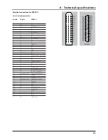
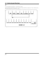
8.5
1a
5
S1+
1b
6
S1-
1c
26
End nozzle L
2a
7
S2+
2b
8
S2-
2c
25
End nozzle R
3a
9
S3+
3b
10
S3-
3c
29
+12V sensor
4a
11
S4+
4b
12
S4-
4c
4
PWM 1TX
5a
14
S5+
5b
15
S5-
5c
27
GND
6a
16
S6+
6b
17
S6-
6c
13
Optional 5 Reg. feedback
7a
18
S7+
7b
19
S7-
7c
33
Option 1 4-20mA
8a
37
S8+
8b
36
S8-
8c
32
Option 2 Frq
9a
35
S9+/Air angle 0-5V
9b
34
S9-/Fan speed 0-5V
9c
not connected
Option 3/Tank gauge
10a
21
On/off+
10b
22
On/off-
10c
not connected
PWM Output option
11a
23
P
11b
24
Pressure-
11c
28
Flow
12a
20
Foam blop 0-5V
12b
1
option 4 Rx
12c
31
Speed
13a
3
FM L
13b
2
FM R
13c
30
Gnd sensor
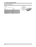
39-p
o
le
37-p
o
le
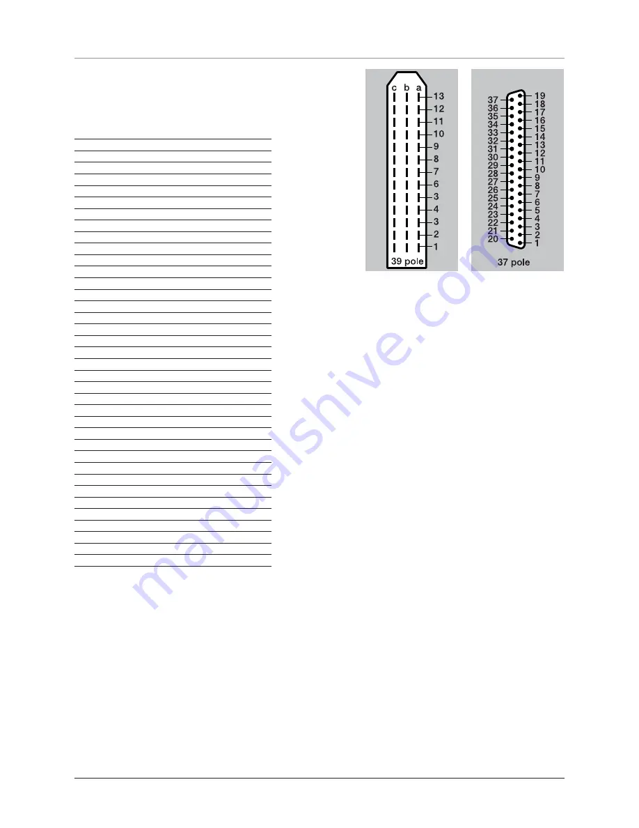
SP
RA
Y II
39
or
37 p
o
led pl
u
g w
it
h
c
a
b
le.
E
le
ctric
al
conn
e
ctions
f
or
SP
RA
Y II
Summary of Contents for Ranger Series
Page 1: ...GLOBAL RANGER Instruction book 67021203 Version 1 00 US 07 2006 ...
Page 2: ......
Page 4: ......
Page 10: ...1 Welcome 1 2 ...
Page 14: ...2 Safety notes 2 4 ...
Page 54: ...6 Maintenance 6 2 Trailer lubrication oiling plan ...
Page 70: ...6 Maintenance 6 18 ...
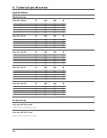
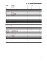
Page 82: ...8 Technical specifications 8 8 Boom hydraulics HZ Boom hydraulics HY Charts ...
Page 83: ...8 Technical specifications 8 9 Boom hydraulics DH ...
Page 84: ...8 Technical specifications 8 10 ...
Page 87: ......


