background image

8 - Technical specifications

47

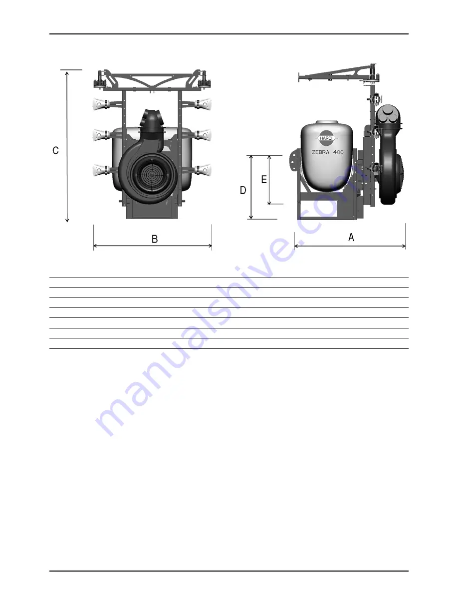
Overall dimensions - ZEBRA ATLAS

Capacity (litres)

300

400

600

800

A (mm)

1350

1350

1400

1400

B (mm)

1490

1490

1490

1490

C (mm)

1930

1930

1930

1930

D (mm)

800

800

910

910

E (mm)

663

663

680

680

Summary of Contents for ZEBRA ATLAS

Page 1: ...ZEBRA Original Instruction book 67026102 100 version 1 00 GB 08 2015 www hardi es ...

Page 2: ...s of the original In the event of any conflicts inaccuracies or deviations between the English original and other languages the English version shall prevail Since it is ILEMO HARDI S A U policy to continually improve our products we reserve the right to make changes in the design accessories specifications and maintenance instructions at any time and without notice ILEMO HARDI S A U is extent fro...

Page 3: ...unit 15 CA operating unit 16 Electric section valves 16 Air equipment 17 Axial fan Technical information 17 Protection grids 17 Engaging Disengaging of the turbine fan 18 Fan transmission 18 Cannon spout 18 Vine sprayer 19 Pneumatic system 19 Hydro pneumatic system 19 4 Start up General information 21 Important Information 21 Unloading the mistblower from the truck 21 Before starting up for the fi...

Page 4: ...sion shaft 35 Service and maintenance intervals 36 General information 36 Every 10 working hours 36 Every 50 working hours 36 Every 100 working hours 36 Every 150 working hours 36 Every 1000 working hours 36 Every 10 working hours Suction filter 37 Every 10 hours of operation Pressure filters 37 Every 10 working hours Nozzles 38 Every 50 working hours Pressure pulsation damper 38 Every 50 working ...

Page 5: ...ensions ZEBRA CANNON 46 Overall dimensions ZEBRA ATLAS 47 Overall dimensions ZEBRA LINER 48 Weights 49 Diaphragm pump model 321 10 50 Other Specifications 51 Axial air fan 51 Pump 51 Filters 51 Temperature and working pressure 51 Materials 51 Recycling 52 Conversion factors SI to Imperial 52 Index Index 53 ...

Page 6: ...Table of Contents 6 ...

Page 7: ...080 Lleida SPAIN declares the following product s was manufactured in conformity with the applicable provisions of the Directive 2006 42 EC on machinery and all the applicable provisions of the Council Directive 2004 108 EC EMC Lleida September 2012 Josep Maria Godia Managing Director ILEMO HARDI S A U ZEBRA ...

Page 8: ...1 EC Declaration 8 ...

Page 9: ...ur HARDI dealer for further information before using the equipment Local law may demand that the operator be certified to use this spray equipment Pleasse comply with the law The tractor seat is the safest area when handling the equipment Wear protective clothing Protective clothing may vary according the chemical product being used Please comply with regulations Wash and change clothes after spra...

Page 10: ... not be used if important parts of the equipment have been damaged including safety devices high pressure hoses etc The safety and efficiency of this machine also depends on the way it is handled The first step is to read carefully and pay attention to this instruction manual as it contains essential information for an efficient use and maintenance of this high quality product As this instruction ...

Page 11: ...used for this purpose The mistblower must not be used for any other purpose If there are no special regulations requiring operators to be certified you must have received the appropriate training on how to spray crops correctly and safely handling chemicals to avoid unnecessary risks to persons and the environment while spraying Road worthiness When driving on public roads and other places where t...

Page 12: ...graph The serial number contains five digits Chassis Manufactured with a tubular profile which provides great durability and resistance to breakages and vibrations To protect it from corrosion it is sanded down and covered with a layer of special paint that contains a polyurethane bi component with anti corrosion additives and protection against ultraviolet rays Tank Made of medium density polyeth...

Page 13: ...liquid circuit as this could put your safety at risk Pressure pulsation damper The 321 pump is fitted with a pulsation damper on suction and pressure sides The pressure side damper is pressurized The dampers will reduce pulsations and secure an even flow from the pump The pressure pulsation damper should be inflated to the pressure shown in the table on top of the pulsation damper A Suction filter...

Page 14: ...Diaphragm pump is model 321 10 max 20 bar with two diaphragms It works at low pressure and is robustly built Use only grease for lubrication This type of pump is self priming works without oil and can run dry as long as necessary Piston pump Certain countries only The robust high pressure piston pumps are fitted with a single block crankcase with a large oil capacity for increased lubrication and ...

Page 15: ...adjustment valve a pressure gauge and two section valves for right and left spray lines Lever A is main on off Red knob B is pressure adjustment valve Clockwise increase Anti clockwise decrease SV 2 operating unit Certain countries only This high pressure electric operating unit contains a manual pressure valve fitted to the machine and a electric control box for opening and closing the section va...

Page 16: ... of pressure equalisation by turning left or right to increase or decrease pressure 4 Pressure filter 5 Pressure regulation manual Electric section valves Two electric solenoid valves are used to control spraying to RH or LH side The valves are controlled by the operating box in the tractor cabin ...

Page 17: ... or modify any of the parts but leave this to your HARDI dealer Any repair jobs on air kits in requires qualified technicians Protection grids On all axial air kit models protection grids are fitted They are fundamental for avoiding accidents and stopping foreign objects from entering the fan A Air inlet protection grid B Air outlet protection grid DANGER Use of the air kit without protection grid...

Page 18: ...ing hours to ensure full performance See the section Maintenance Cannon spout The ZEBRA is available in a configuration with a cannon spout This allows for the entire volume to be directed in one direction The spout is horizontally adjustable and can be turned to both sides The air outlet of the Cannon is ellipsoidal in order to create a large and powerful air stream in the upper part for blasting...

Page 19: ...he mist is distributed uniformly in the shape of a fan Four types of spouts are available depending on boom type A Cannon with 1 outlet B Spout with 2 outlets C Spout with 3 outlets D Spout with 4 outlets Ceramic discs are used to control the flow rate This disc has two positions If the disc is placed so the flow enters through its flat side this will allow less to go through than if it enters thr...

Page 20: ...3 Description 20 ...

Page 21: ...and below or next to the machine during loading or unloading Before starting up for the first time Although the surface of the metallic parts of the mist blower have been coated with a strong protective product we recommend you apply a layer of anti corrosion oil e g CASTROL RUSTILLO or SHELL ENSIS FLUID to all metal parts to avoid chemical products discolouring the enamel as well as to ease futur...

Page 22: ...INE and remove the ignition key before carrying out maintenance or repairs to the transmission shaft or implement DANGER ROTATING TRANSMISSION SHAFTS WITHOUT PROTECTION GUARDS ARE FATAL P T O installation Initial installation of the driveshaft may involve having to cut the axle to adapt it to the tractor to which it will be hitched To hitch it for the first time proceed as follows 1 Attach the mis...

Page 23: ... the mistblower lower link pins 2 Fit the linch pins to secure the lower links 3 Attach the top link to tractor and mistblower and adjust it by hand Secure with a linch pin 4 Lift the mistblower to working height 5 Ajdust the top link until the equipment is completely perpendicular to the ground To detach the mistblower 1 Lower the tractor s lower links with the hydraulic lever until the equipment...

Page 24: ... ref no 637348 can be mounted on the frame of the NK 600 litre model to enable the snap coupler to be connected on the top link of the mistblower 1 Loosen the 4 bolts which fix the top link to the tank frame 2 Replace this top link with the adapter clevis and fasten it to the frame with the 4 bolts ...

Page 25: ...ly connector the supplied connector will need to be removed and adapted to the tractor connector Installing the basic electrical control box Find a suitable location in the tractor cabin where the control box can be fitted and operated comfortably It is recommended that you place it to the right of the driver s seat μ ATTENTION The control box must be properly attached to prevent vibrations and da...

Page 26: ...4 Start up 26 ...

Page 27: ...water supplies for drinking purposes treatment sumps and cesspools of drainage systems and 3 50 metres from surface water watercourses lakes and coastal waters and from nature reserves B Alternatively the mistblower can be filled in the field where the spraying is to take place If so choose a different location for each refilling C If no other requirements of distances exist the filling should not...

Page 28: ...s in good condition and lubricated Pressure filter Pressure filters will catch any remaining impurities and prevent nozzles clogging To avoid blockage of those filters it is very important to check them regularly and clean them after each spray job to avoid chemical residues to deposit and block WARNING Wear appropriate personal protection when checking pressure filters As a minimum gloves and fac...

Page 29: ...ould be as clean as possible to obtain best results Fill the tank using the filter to prevent impurities from entering the tank For greater filling capacity an overhead tank can be used The tank should be filled to a third of its capacity with clean water before adding the chemical product Always follow the instructions given on the product label μ ATTENTION Always fill through the tank strainer t...

Page 30: ...ff position for the section or sections to be closed Note that the pressure will rise and readjustment will be necessary Adjustment of operating unit SV 2 This high pressure electric operating unit can be assembled with piston or diaphragm pumps It consists of a manual pressure valve that has a pressure gauge To raise the pressure turn the red handle A clockwise To lower it turn it anti clockwise ...

Page 31: ... To close it again turn the pin again and the valve will close automatically 400 600 and 800 l tanks Top operated tank drain A open B Close WARNING Do not forget to use protective clothing and gloves when doing this Agitation The dual nozzle agitation system injects the chemical product at high pressurefrom the pump inside the tank creating a turbulence that mixes the product with the water to a u...

Page 32: ...le before engaging the PTO Nozzles The standard nozzle can be closed individually by turning them 90º When open the direction can be adjusted within a range of 15º A non drip valve A is fitted to avoid chemical spillage the sections are shut off The nozzle type B are a hollow cone nozzle also known as ATR They are colour coded and the working range is 5 15 bar This type of nozzle can also be used ...

Page 33: ...r a larger cultivated area see also Filling washing location requirements on page 27 4 Cleaning starts with the calibration as a well calibrated sprayer will ensure the minimal amount of remaining spray liquid 5 It is good practice to clean the sprayer immediately after use and thereby rendering the sprayer safe and ready for the next pesticide application This also prolongs the life of the compon...

Page 34: ...n valves until last Some detergents and deactivating agents work best if left in the tank for a short period Check the label 8 Drain the tank and let the pump run dry Rinse inside of the tank again letting the pump run dry 9 Stop the pump If the pesticides used have a tendency to block nozzles and filters remove and clean them immediately 10 Replace all the filters and nozzles and store the mistbl...

Page 35: ... be used see Recommended lubricants 2 Recommended intervals hours μ ATTENTION If the sprayer is cleaned with a high pressure cleaner lubrication of the entire machine is recommended Recommended lubricants Transmission shaft The universal joints and needle bearings should be lubricated with grease At the points shown you should do A every 8 working hours and the profile tubes B every 20 working hou...

Page 36: ...ck for leaks on the suction circuit Every 50 working hours 1 Carry out the checks mentioned above 2 Check the pressure in the pressure pulsation damper 3 Check Grease the transmission shaft 4 Check grease the mechanical clutch 5 Grease the diaphragm pump 6 Check oil level on piston pumps Every 100 working hours 1 Carry out the checks mentioned above 2 Check adjust the fan transmission V belts tigh...

Page 37: ...rs leads to numerous unwanted stops during a working day μ ATTENTION Lubricate the seal lightly with oil or grease every time the filter is dismantled to ensure the seal will slide correctly in place and seal μ ATTENTION A broken or leaking O ring or sealing in the suction circuit leads to suction of false air and huge vibrations and pressure pulsations Every 10 hours of operation Pressure filters...

Page 38: ... insufficient results Every 50 working hours Pressure pulsation damper The 321 pump is fitted with a pulsation damper on suction and pressure sides The pressure side damper is pressurized The dampers will reduce pulsations and secure an even flow from the pump The pressure pulsation damper should be inflated to the pressure shown in the table on top of the pulsation damper A Every 50 working hours...

Page 39: ...suitable tightness Tighten the bolts equally in both sides 4 The V belt should yield 10 15 mm by a force of 10 N 1 kg halfway between the two pulleys 5 Tighten the counter nuts again 6 Tighten the 2 x 3 fan retaining bolts either side again μ ATTENTION Over tightening the V belts will increase load wear and tear on the pump and fan parts and bearings Every 150 working hours Piston pump oil change ...

Page 40: ...are not to fit valves on upside down 7 Fit the diaphragm cover again When the cover is placed on top of the diaphragm and before the bolts are tightened turn the crankshaft one turn to seat the diaphragm correctly in the cover Torque settings for the 321 are Crankcase 60 Nm 44 4 lbft Crankshaft 70 Nm 51 8 lbft Diaphragm screws 60 Nm 44 4 lbft Piston pump Plunger tightness When you detect a continu...

Page 41: ... a quarter of a turn with key if you have torque wench tighten the torque to 2 5 3 kg pressure approximately 30 Nm μ ATTENTION Before replacing it be aware that the leather gives over time in the sleeve and dripping can occur If this happens tighten the leather tensor and the liquid will stop dripping 7 Fit the cylinder heads and place the nuts without over tightening them 8 Grease the joints of t...

Page 42: ...etallic parts from drying up during the period of time that the equipment will be out of use Preparing the equipment for use after storage After storage the equipment should be prepared well thus guaranteeing it is in good condition for the new season To do this correctly follow the steps set out below 1 Take off the protective canvas cover if you had put one on 2 Fit the pressure gauge again Chan...

Page 43: ...zles 5 Impurities sucked by the pump may prevent the valves from closing correctly thus reducing the pump flow 6 A bad reassembly of the pump elements especially the diaphragm covers causes air intakes or leaks and reduces the pump flow 7 A badly charged or faulty battery causes failures and misbehaviour in the electrical system Therefore ALWAYS check 1 Suction and pressure filters as well as nozz...

Page 44: ...ction clogged Check the suction tube Air suction Reduce revolutions in the PTO Increase in pressure Pressure filters blocked Clean the filters Foam formed Air in the circuit Check the o rings gaskets hoses and suction fittings Excessive agitation Reduce revolutions in the PTO Check the voltage of the safety valve of the self cleaning filter Make sure that there is return to the tank Use anti foami...

Page 45: ...ications Dimensions Overall dimensions ZEBRA AXIAL Capacity litres 300 400 600 800 A mm 1432 1432 1600 1600 B mm 901 1020 1200 1600 C mm 1222 1102 1554 1554 D mm 712 712 825 825 E mm 483 483 596 596 F mm 820 1020 1200 1600 ...

Page 46: ...chnical specifications 46 Overall dimensions ZEBRA CANNON Capacity litres 300 400 600 800 A mm 1350 1350 1400 1400 B mm 1250 1250 1250 1250 C mm 1555 1555 1555 1555 D mm 800 800 910 910 E mm 663 663 680 680 ...

Page 47: ...chnical specifications 47 Overall dimensions ZEBRA ATLAS Capacity litres 300 400 600 800 A mm 1350 1350 1400 1400 B mm 1490 1490 1490 1490 C mm 1930 1930 1930 1930 D mm 800 800 910 910 E mm 663 663 680 680 ...

Page 48: ...chnical specifications 48 Overall dimensions ZEBRA LINER Capacity litres 300 400 600 800 A mm 1350 1350 1400 1400 B mm 1250 1250 1250 1250 C mm 1555 1555 1555 1555 D mm 800 800 910 910 E mm 663 663 680 680 ...

Page 49: ... Full kg 510 630 860 1080 ZEBRA CANNON Capacity litres 300 400 600 800 Empty kg 200 220 320 345 Full kg 500 620 920 1145 ZEBRA ATLAS Capacity litres 300 400 600 800 Empty kg 230 250 340 365 Full kg 530 650 940 1165 ZEBRA LINER Capacity litres 300 400 600 800 Empty kg 230 250 340 365 Full kg 530 650 940 1165 ...

Page 50: ...n kW l min kW l min kW l min kW l min kW l min kW 0 39 0 3 52 0 4 65 0 5 70 0 6 78 0 7 91 0 8 5 39 0 3 52 0 5 65 0 6 70 0 6 78 0 7 91 0 8 10 39 0 7 52 0 9 65 1 1 70 1 2 78 1 4 91 1 6 15 39 1 0 52 1 4 65 1 7 70 1 8 78 2 0 91 2 4 20 39 1 4 52 1 8 65 2 3 70 2 4 78 2 7 91 3 2 25 39 1 7 52 2 3 65 2 8 70 3 0 78 3 4 91 4 0 ...

Page 51: ...above 20 C Weight 19 kg Filters Suction 35 mesh 0 6 mm Pressure 50 mesh 0 3 mm Temperature and working pressure Temperature from 2ºC to 40ºC 36ºF a 104ºF Maximum pressure in the suction MANIFOLD 7 bar Maximum pressure inside the MANIFOLD 30 bar Materials Tanks PE MD UV resistant Hoses PVC or rubber Valves PA with carbon fibre Fittings PA Fan Wings PA with glass fibre and aluminium Turbine Galvaniz...

Page 52: ...gislation Conversion factors SI to Imperial All units used in this instruction book are SI In some cases imperial units are used Use these factors to convert between SI and Imperial units SI unit Imperial unit Factor Weight kg lb x 2 205 Surface area ha acres x 2 471 Length cm in x 0 394 m ft x 3 281 m yd x 1 094 km mile x 0 621 Speed km h mile h x 0 621 km h m s x 0 277 Volume Surface area l ha g...

Page 53: ...r Box 18 H Hooking up 23 HPC Circuit 15 Hydro pneumatic System 19 I Identification plates 12 Imperial 52 Interruptions 34 L Leakage piston pump plungers 40 Liquid circuit 27 Liquid system 13 Lubricants recommended 35 Lubrication 35 42 M M70 2 15 Materials 51 Mistblower 11 N Nozzles 32 O Oil level piston pump 39 Operational problems 43 Operator safety 9 22 Overview 11 P Plunger replacement piston p...

Page 54: ...Index 54 ...

Page 55: ...l parts information can be accessed in the spare parts catalog 1 Go to www agroparts com register for free and log in 2 Select HARDI in the menu on the left 3 Select Spare parts catalogue and find your spare part 4 Online ordering is also possible 5 Contact your HARDI dealer for further information on spare parts ...

Page 56: ...ILEMO HARDI S A U Poligono Industrial El Segre 712 713 25080 Lleida SPAIN ...

Reviews: