


15
3 - Description
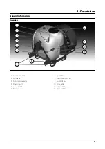
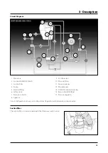
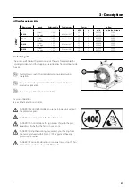
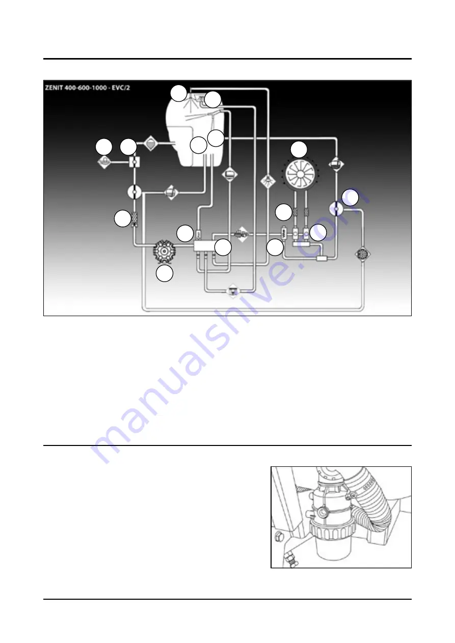
Circuit Diagram
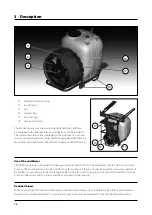
1. Main tank
2. Suction MANIFOLD (black)
3. Suction filter
4. Pump
5. External filling
6. Safety valve
7. Pressure collector
8. Agitation
9. Section valves
10. Pressure filters
11. Fan and nozzles
12. Powder mixer
13. Nozzle for internal cleaning
14. Return Manifold (Blue)
15. Pressure regulator
Circuit configuration can vary according to local legislation and standards, e.g. dump valve.
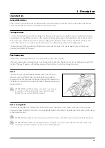
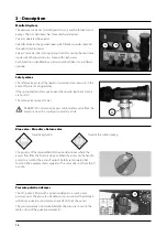
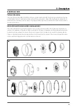
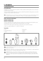
Suction filter
The suction filter is located underneath the three-way suction valve.
1
2
3
4
6
12
8
13
7
15
10
9
14
11
5
Summary of Contents for ZENIT 400
Page 2: ......
Page 4: ......
Page 10: ...6...
Page 117: ......
Page 118: ...ILEMO HARDI S A U Poligono Industrial El Segre 712 713 25080 Lleida SPAIN...


