background image

82

6 - Maintenance

Variant boom

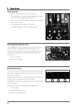
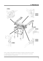
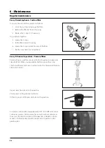
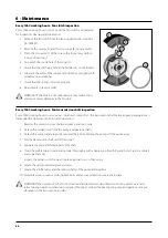
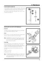
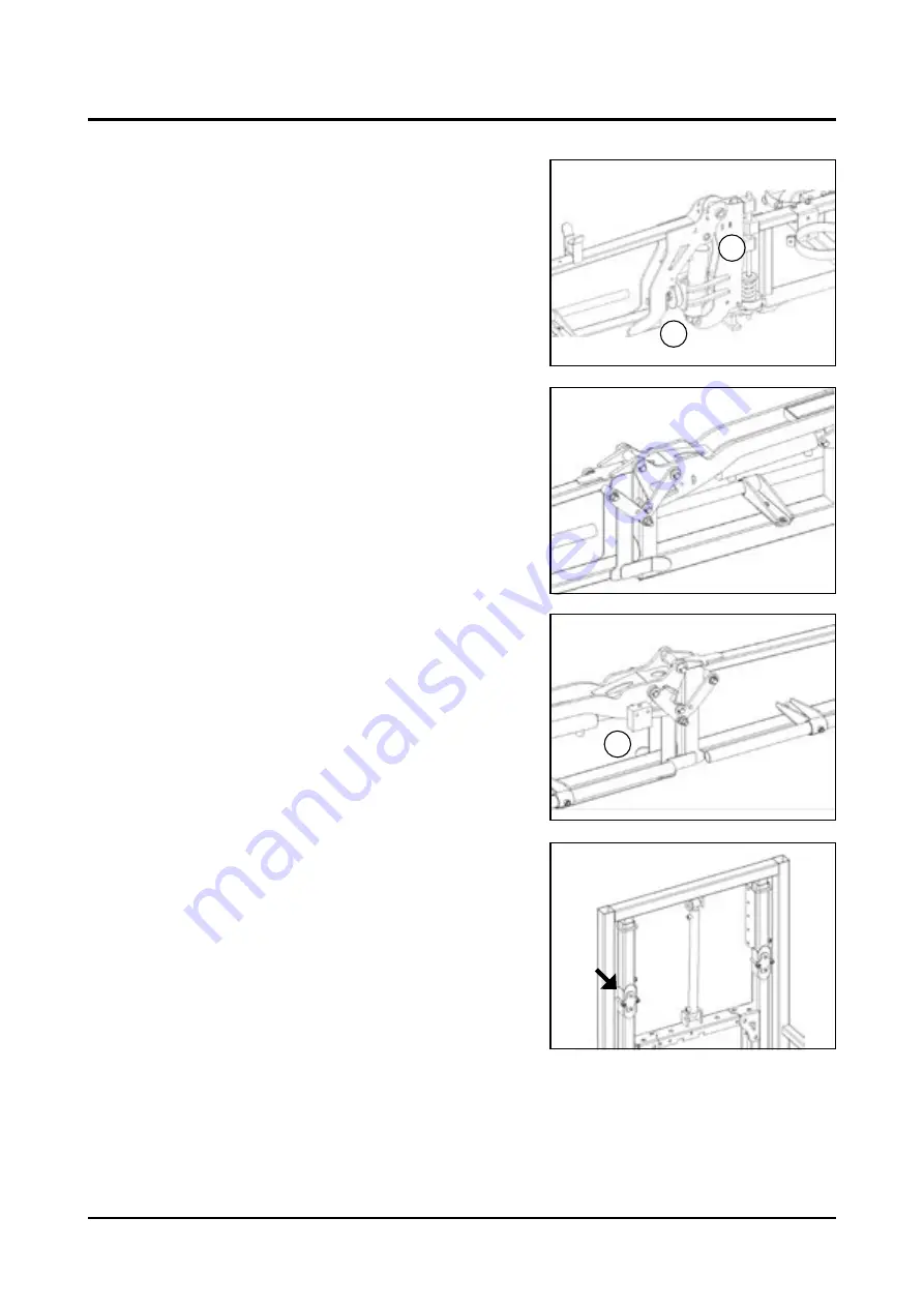
The shock absorber A   is adjustable to secure the boom in horizontal 
position when unfolded, loosed the loos the two nuts on the main 
bolt, adjust to reach horizontal position.

The brake away B clutch need to be adjusted in tension, according to 
driving conditions. 

All pivoting points need grease or oil every 150 hours 

To secure the folding sequence of the bi folded booms, a by pass valve   
C   is mechanical activated when the hinge touch it.

The position of the by pass valve might needs adjustment t secure 
the folding sequence. Loosen the two 8 mm bolt from the back side, 
position the by pass valve in such a way , to be activated the outer 
boom wing in folded over inner section

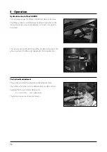
The hydraulic upright has two nylon skeet, that needs adjustment 
according to wear and tear.

The skeet need just to be 0,5 mm near the telescoping part. 

C

A

B

Summary of Contents for ZENIT 400

Page 1: ...ZENIT Original Instruction book 67025002 200 Version 2 00 GB 09 2015 www hardi es www hardi international com...

Page 2: ......

Page 3: ...er to make this infor mation as complete and correct as possible As this instruction book covers models specifications or equipment that are only available in cer tain countries please pay particular...

Page 4: ......

Page 5: ...m 15 Suction filter 15 Safety valve 16 Pressure manifold 16 Suction and pressure pulsation dampers 16 Agitator 16 Operating unit 17 MC 2 operating unit 17 SV operating unit 17 CB operating unit 17 Fil...

Page 6: ...er DB 3620 41 Fluid circuit 42 Suction filter 42 Pressure damper 42 Diaphragm pump 42 Deflectors 43 Booms 45 General information 45 FIX 45 START 45 ATLAS START 46 ATLAS AGILE 46 ATLAS SOLID FIX and AT...

Page 7: ...3014 etc 67 FB 3610 67 CB operating unit 68 CB operating unit with by pass valve 68 Hydraulic control boxes 68 HB 3610 69 The Joystick S selector 69 Cannon L M T 69 Hydraulic control of the CANNON 70...

Page 8: ...r adjustment 93 Replacing the valves and 363 and 463 diaphragms 93 Lubrication 94 General information 94 Grease Gun Calibration 95 Greasing the Pump 95 Service and Maintenance Intervals 96 50 Hours Se...

Page 9: ...da SPAIN Declares the following product s NEPTUN ZATURN JUPITER hare manufactured in conformity with the applicable provisions of the Directive 2006 42 EC on machinery and all the applicable provision...

Page 10: ...6...

Page 11: ...formation before using the equipment Local law may demand the operator to be certified to use this spray equipment Comply with the law The tractor seat is the safest area when handling the equipment W...

Page 12: ...machine is turned on Always replace all safety devices or shields immediately after servicing Disconnect the power supply before servicing and de pressurise the equipment after use and servicing If a...

Page 13: ...Overview 1 Clean water tank 2 Main tank 3 Front level indicator 4 Operating Unit 5 3 point hitch 6 Pump 7 Quick hitch 8 Attachment lift arms 9 Suction filter 10 Rinse tank 11 Rinse tank cap 12 Main t...

Page 14: ...HARDI mistblower is designed for applying crop protection chemicals The equipment should only be used for this purpose The mistblower must not be used for any other purpose If there is no special reg...

Page 15: ...there are other special rules and regulations for marking and lights on machinery the machine must be equipped to comply with these regulations ATTENTION For models not fitted with brakes the maximum...

Page 16: ...3000 l A large easy to read tank contents indicator is placed on the front right hand side and another one is placed on the left side First one is visible from the tractor cabin The filling hole is a...

Page 17: ...built Use only grease for lubrication The 363 model has six diaphragms and the 321 has two This type of pump is self priming works without oil and can run dry as long as necessary Valves The suction...

Page 18: ...s lead back to tank via hose A The safety valve opens at15 bar DANGER Do not remove bypass or block safety valve from the liquid circuit as this could put your safety at risk Blue valve Blue disc Retu...

Page 19: ...9 Section valves 10 Pressure filters 11 Fan and nozzles 12 Powder mixer 13 Nozzle for internal cleaning 14 Return Manifold Blue 15 Pressure regulator Circuit configuration can vary according to local...

Page 20: ...d is situated on the front of the machine next to the operating unit From this manifold it is possible to activate the agitator and the rinsing nozzle for internal cleaning optional Suction and pressu...

Page 21: ...ectrical remote pressure regulation section valves by means of motor valves with pressure equalization device Filters The pressure filters are located on the bumper next to the air outlet nozzle In th...

Page 22: ...n chemicals are to be filled into the TurboFiller TurboDeflector valve This TurboDeflector valve activates the Vortex flushing of the TurboFiller Lift the lever to lock it in open position for continu...

Page 23: ...tart and stop EF820 EF920 AB750 AB820 AB920 AG820 and AG920 The air kits are fitted with a grid with air guides at the air intake which forms the air flow before reaching the fan to decrease the imbal...

Page 24: ...n Some objects may be shot out of the air outlet or a piece of clothing could be sucked into the air inlet The fan is the most dangerous part of the machine Do not try to replace any of the parts with...

Page 25: ...dents and for stopping foreign bodies from getting inside the air kit Tractor drivers seat is the intended working place during operation This product is designed and should be used in orchard product...

Page 26: ...a 2 speed gear box with a neutral position The front and lower area of the gear box are attached to the chassis It is fitted with a speed selector that prevent from jumping out of gear when engaged Th...

Page 27: ...icians Adjusting the fan The angle of the fan blades can be adjusted to 4 positions The factory setting is normally pos 3 Decreasing the blade angle minimum angle position 1 reduces the flow and power...

Page 28: ...ts The following section gives more details about the different pneumatic air kits available The letters HF D means High Flow and Double respectively They have a polyethylene crankcase Crankcase and t...

Page 29: ...d The blower units have protective grids fitted to the air inlets They are essential for avoiding accidents and preventing small stones leaves or other foreign bodies from entering the blower unit tha...

Page 30: ...ed to turn at a maximum of 540 r p m The clutch is in the centre of the turbine which ensures smooth start up and stop See section Clutch for further information Clutch All blower types The clutch is...

Page 31: ...4 booms programs LINER ATLAS BOXER or CRONOS The booms are equipped with pneumatic or hydro pneumatic spouts or IRIS drop legs If hydraulic folding and adjustment is offered it is direct to the tracto...

Page 32: ...g versions START AGILE and SOLID According to specification hydraulic adjusted The SOLID addition is as well offered in a GV version Geometry Variable ATLAS AGILE ATLAS SOLID CONVERT ATLAS SOLID GV FI...

Page 33: ...ure and SOLID is reinforced and wider boom structure BOXER SOLID HORIZONTAL FIX BOXER SOLID VERTICAL FIX BOXER SOLID HORIZONTAL CONVERT BOXER SOLID VERTICAL CONVERT BOXER START HORIZONTAL H2 BOXER STA...

Page 34: ...IA has trapeze suspension All 3 versions of the CRONOS boom are offered in FIX boom wing no angling Tilt function in boom wing or GV boom wing Geometry Variable allows Tilt up in positive 60 and negat...

Page 35: ...riant boom The boom is offered from 7 to 13 m hydraulically folded fitted with pneumatic or hydra pneumatic spray spout Boom up to 7 m are cross folded larger boom are bi articulated and folds paralle...

Page 36: ...sen counter nut A loosen bolt B To tighten clutch to be harder loosen nut A tighten bolt B Tightness must never be harder than 15 Kg 30 pounds or the outer boom wing will open activate the boom clutch...

Page 37: ...stributed uniformly There are two Paraflow models which cannot be used together according to the bar type and assembly requested for the machinery Paraflow tube with 4 in line atomizers Paraflow tube...

Page 38: ...the air supply if necessary The IRIS system provides the required droplet size and air conduction to the target The most delicate and difficult part of the vine the grape cluster is safely treated th...

Page 39: ...for the first time Although the surface of the metallic parts of the mist blower have been coated with a strong protective product we recommend you to apply a layer of anti corrosion oil e g CASTROL R...

Page 40: ...the other to the mistblower crankshaft and measure out the length that needs to be removed Mark the protection guards ATTENTION The shafts must always have a minimum overlap of one third of their wor...

Page 41: ...wo hooks will close automatically and the equipment will be fixed to the tractor 8 Put the safety pins of the semi automatic quick hitch on to avoid the equipment from becoming detached during transpo...

Page 42: ...3D double acting outlets etc Converted to 1 Double acting outlet All booms offer optionally a Small Joystick S3 or S5 to cover up to 5 double acting functions into just 1 double acting outlet Larger b...

Page 43: ...ight of the driver s seat The control box must be properly attached to prevent it from being hit or from excessive vibrations The connector type is universal and it should be able to be connected to a...

Page 44: ...40 4 Starting up Rate controller Rate controller DB 3610 Display DB 3610 Fluid Box FB 3610 Hydraulic box HB 3610 Power BOX out put out put The Job boxes for input and out put signals...

Page 45: ...41 4 Starting up Rate controller DB 3620 Display DB 3620 Fluid Box FB 3620 Hydraulic box HB 3620 Power BOX The Job boxes for input and out put signals out put out put...

Page 46: ...alse air Pressure damper The air pressure of the pulsation damper 321 pump is factory set at 2 bar to match spraying pressures between 3 and15 bar When spraying with different pressures than this you...

Page 47: ...ent bolts test with clean water And verify target is well sprayer Top S or L S the short version L the slightly higher version Parked between rows orientate the adjustable air outlet towards the targe...

Page 48: ...cure direction of air and spray mist towards the target Loos the hand wheel position the adjustable part in visual direction to the target tighten up the hand wheel and test with clean water JET defle...

Page 49: ...tioning the spray device and tightening again Width adjustment from 7 to 40 START Provides telescopic width adjusted by loosening the bolt in pos X Once positioned tighten the bolts again Width adjust...

Page 50: ...sides Loosen up fixation bolt in mentioned A and B area adjust and tighten again ATLAS AGILE Boom wing width as ATLAS START but combines with the FIX boom bracket ATLAS SOLID FIX and ATLAS SOLID FIX G...

Page 51: ...iption under ATLAS START BOXER SOLID VERTICAL FIX or CONVERT Telescopes from 11 8ft to 15 7ft or 3 6m to 4 8m Rear part FIX or CONVERT side adjustment consults the respectively description above BOXER...

Page 52: ...0 hours or annually The indicated nylon friction parts must be kept clean avoid sand and dust in them Replace when worn CRONOS BOOM Exist as SOLID RIDER GV or VARIA SOLID 7 1 me boom width the spray d...

Page 53: ...and to the right side Secure the telescoping part is well lubricated and all ways kept clean from sand and dust The telescoping part is guide in nylon friction pads secure they are in proper Once the...

Page 54: ...B To tighten clutch to be harder loosen nut A tighten bolt B Tightnes must never be harder than pusc of 15 Kg 30 pounds on the outer boom wing will open activated the boom clutch Adjustment of hydrau...

Page 55: ...be adjusted for slack between the male and feel tubes Tighten on the two indicated nuts just to make it press gently on the inner male tune if too tight it will not be moveable too loos it will have d...

Page 56: ...o correct position tighten bolt again Adjustment of inner 4 spray device The optional S bracket as indicated by the arrow in the photo can be mirrored 180 Thereby the spray device is able to be positi...

Page 57: ...he spray mist that all nozzles stops instantly and do not spill on the ground The nozzles B are fitted in an adjustable support in order to angle them forward accordingly to forward speed and there by...

Page 58: ...In addition to these nozzles there are three adjustable nozzles outside the spout which allows to treat the nearby crops also Model M is fitted on variants with two turbines It comprises an outlet of...

Page 59: ...ipment immediately and have it serviced by an authorised HARDI technician Selecting the gear The low or high gear can be selected using the specially designed lever On the rear left hand side of the m...

Page 60: ...auto destroy structure due to movements caused from lack of firm position See maintenance and starting up Adjustment of hydraulic fold Secure folding cylinder is correctly adjusted and eventually stop...

Page 61: ...of the fan 3 With both hands on opposite blades turn them to the desired position between 1 and 4 All the blades should turn at the same time 4 Finally check that all the blades are in the correct pos...

Page 62: ...r watercourses lakes and coastal waters and from nature reserves B Alternatively the sprayer can be filled in the field where the spraying is to take place If so choose a different location for each r...

Page 63: ...ters and from nature reserves B Alternatively the sprayer can be filled in the field where the spraying is to take place If so choose a different location for each refilling If no other requirements o...

Page 64: ...er to a uniform liquid The standard agitation has 2 mm ventury nozzles The ventury nozzle B allows an effecient agitation of the main tank content Clean water tank The clean water tank is located at t...

Page 65: ...l legislation in force at any time ATTENTION The water supply should be provided with a meter to avoid spillage by over filling Follow local legislation in force at any time Filling the rinsing tank T...

Page 66: ...ean water tank The clean water tank is located at the front and integrated in the main tank design It is used for washing hands gloves and cleaning clogged nozzles etc WARNING Although this tank is co...

Page 67: ...fan gear lever to neutral position engage the pump and set P T O at 540 r min 4 Open TurboFiller lid Measure the correct quantity of chemical and fill it into the hopper 5 Engage the hopper transfer...

Page 68: ...r and chemical containers are done in the following two ways When TurboFiller lid is open For cleaning empty containers Put container over the rotating flushing nozzle in the middle of the TurboFiller...

Page 69: ...tivated Air condition on off ventilator on the radiator on off etc That auxiliation in voltage do affect the Spray Computer Installation of control unit brackets Find a suitable place in the tractor c...

Page 70: ...he pressure in the remaining spray line change 1 Section valves When up off When down on 2 Pressure up down for less pressure for higher pressure an optional function SV operating unit 1 Manual pressu...

Page 71: ...in order to obtain pressure equalisation Cleaning the pressure filter 4 Stop the tractor engine Unscrew they filter by turning left Wash the filter in soap water put it back in to the filter body and...

Page 72: ...l bypass valve Open the valve to let X amount pump flow return freely to tank this provides a pressure drop in the system and allows the pressure to come very low Clock wise closing Anti clock wise op...

Page 73: ...t fitted inside the Joystick Connect the power plug to 12 V and connect the universal connection plug to the sprayer Push the leaver joystick forward without pressing a button and the lift goes up upp...

Page 74: ...10 to 80 compared to horizontal The spout can be rotated180 by another double acting outlet This allows treatment to either side independet of driving direction The hydraulic adjustment The joystick a...

Page 75: ...essure Also access to Settings the menu where time delay and respond time to vegetation sensors are programed See separate manual 4 Automatic or manual mode of the on off function if vegetation sensor...

Page 76: ...real P programed 21 Remaining capacity according to tank level 22 Time 23 Tank level 24 Rate controller in ON or OFF 25 Optional vegetation sensors 26 Section of operating unit Above picture illustra...

Page 77: ...is 9 Bar If speed is higher than 6 km h the rate controller will not push up the pressure as the programed max speed is 6 km h Spray mist continues to flow through the nozzles when we are beyond the l...

Page 78: ...he adjustment by opening both sections at the same time or one by one If the operating unit is correctly adjusted the pressure always remains unchanged ATTENTION It is recommended to carry out this ad...

Page 79: ...e or runoff of residue into watercourses wells springs pools etc The fluid remaining after rinsing the equipment cannot be disposed of down a sewer It must be emptied into a suitable soakaway 4 Cleani...

Page 80: ...es lakes and coastal waters and from nature reserves B Alternatively the sprayer can be filled in the field where the spraying is to take place If so choose a different location for each refilling If...

Page 81: ...e been in contact with the chemical Before opening the distribution valves and spraying the liquid out decide whether this should be done in the field again or on the soakaway 6 After spraying the liq...

Page 82: ...empty close the TurboFiller suction valve again VI Turn the suction valve towards Main tank and the pressure valve towards Spraying and spray the liquid in the field just sprayed Cleaning of Main tan...

Page 83: ...Close AgitationValve no agitation 3 Engage the pump and spray the water from the rinsing tank in the field until all nozzle tubes nozzles have been flushed with clean water 4 Disengage pump again ATTE...

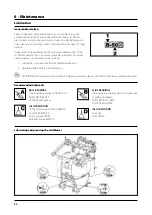
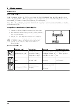
Page 84: ...on lubrication are as follows 1 Lubricants to be used See Recommended lubricants 2 Operating hours before next lubrication ATTENTION If the sprayer is cleaned with a high pressure water cleaner the w...

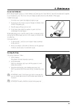
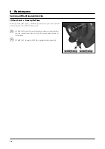
Page 85: ...pivoting telescoping and moveable parts on all boom and spout types every 100 hours It is a general illustration functions such as Varia and others might not be present on your machine Stop tractor e...

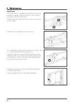
Page 86: ...every 150 hours To secure the folding sequence of the bi folded booms a by pass valve C is mechanical activated when the hinge touch it The position of the by pass valve might needs adjustment t secur...

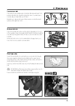
Page 87: ...d every 50 hours to avoid unnecessary wear and tear When the chain is worn it is recommended to change all parts as a new chain on worn sprockets will wear faster Diaphragm pump Grease the pump every...

Page 88: ...he season some extra time should be dedicated to the equipment before storing it during the winter time It is recommended you store it in a place where it cannot be affected by freezing temperatures P...

Page 89: ...e transmission shaft protection guard Replace any damaged parts as required Re tighten the bolts of the wheels and the areas under the greatest stress or torque Check adjust tyre pressure Check adjust...

Page 90: ...ove the pressure filter unscrew the filter housing to inspect and clean the filter When you reassemble the filter grease the o ring There are different mesh sizes See the section Technical specificati...

Page 91: ...ed when their unit flow varies more than 10 Worn or damaged nozzles may cause crop damages or insufficient results Every 1000 working hours Gearbox oil change Change the oil after the first 150 workin...

Page 92: ...he transmisson shaft between pump and gearbox is dismantled for cleaning inspection and lubrication 1 Remove the protection cover between pump and main tank 2 Detach the cardan joints from the pump an...

Page 93: ...haft with the hand and make sure that the connecting rods are ascending and decending respectively If not change the position of the connecting rods The first connecting rod must be assembled towards...

Page 94: ...herefore the motor keep turning unlimited It will burn the fuse Pull out the clip as illustrated lift gently up the gear motor replace the micro switch as illustrated in the picture showing the gear m...

Page 95: ...up to overlap the last notch on valve body Screw on and lock up to beat the nut holding the handle while tightening WARNING to operate the gear motor unit 1 install 1 25A fuse on 12Vdc line The mark...

Page 96: ...ntation to built up If it built up and drop of in uneven locations it creates unbalance in the air kit and destroys drive line and the air kit it self Rinse the fan blade and inner fan house wall and...

Page 97: ...correctly afterwards ATTENTION When you remove the crankcase covers you will see that there are 2 valves that are slightly different from the rest For correct operation remember to fit them in the sa...

Page 98: ...be used see Recommended lubricants below 2 Recommended intervals Shown in hours or with a symbol for occasional maintenance 3 Amount to be used Only shown if an amount is specified ATTENTION If the sp...

Page 99: ...plete when lubricating the different grease points on the sprayer according to the specifications Alternative method 1 Count the strokes until you have 10 grams of grease piled up on the scale A 2 Now...

Page 100: ...When operating the pump it MUST be greased every 50 hours with 30 gram grease into each lubrication point ATTENTION In order to avoid excessive wear it is important to use a recommended lubricant See...

Page 101: ...e heads A WARNING To avoid damages in case of a free falling pump use lifting gear and a steel shackle with at least 3 5 tonnes max tensile strength NOTE Pump weight is approximately 75 kg Pump Valves...

Page 102: ...hragm bolt 5 90 Nm 11 Refit the plastic covers C NOTE The diaphragm bolt on 1000 r p m pumps must be secured with locking compound ATTENTION Before tightening the 4 bolts for the head 2 the diaphragm...

Page 103: ...hetic bearings and the protection guard 3 R emove the inner bush from the protection guard 4 Re assemble in the reverse order using new parts if necessary Remember to assemble the chains again 5 Greas...

Page 104: ...the mistblower 2 Replace the o rings and repair any possible leaks 3 Empty the mistblower completely and let the pump work for five minutes Open all the valves to drain as much water as possible from...

Page 105: ...roceed as follows 1 Remove the tarpaulin protecting the machine if there is one 2 Fit the pressure gauge again Replace the old Telfon tape 3 Connect the equipment to the tractor including electric wir...

Page 106: ...mpletely This reduces the pump s performance 5 Poorly re assembled pumps especially diaphragm housings causes the pump to suck air and hence reduces or decreases the pump suction 6 Hydraulic component...

Page 107: ...roduct is being used check that agitation is on Worn nozzles Check that the air flow does not exceed 10 Tank suction clogged Check the suction tube Air suction Reduce revolutions in the PTO Increase i...

Page 108: ...that hold the air kit are loose Tighten the nuts The clutch pads are broken or worn Change the pads and the clutch springs or replace the clutch for a new one Vibrations or noises in the gearbox The...

Page 109: ...cuit In the event of power fault the CB operating unit can be used manually First disconnect the wire from the control box Then manually turn the green throttle valve on each electric motor to open or...

Page 110: ...274 741 513 981 365 600 1542 1798 1200 1350 741 513 1200 372 1000 1880 2013 1426 1612 926 678 1430 430 1200 1880 2013 1615 1708 926 678 1430 450 A B C D E P Kg 400 2000 2050 2300 892 663 365 600 2000...

Page 111: ...3 7 Pump model 321 10 SI unit Imperial unit Factor Weight kg lb x 2 205 Surface area ha acres x 2 471 Length cm in x 0 394 m ft x 3 281 m yd x 1 094 km mile x 0 621 Speed km h mile h x 0 621 km h m s...

Page 112: ...45 3 7 50 3 7 25 22 3 0 30 3 3 37 3 6 40 4 0 44 4 8 50 4 8 Maximum pressure 25 bar Weight 23 2 kg Normal working revolutions 540 r p m 321 10 r min 300 400 500 540 600 700 bar l min kW l min kW l min...

Page 113: ...3 80 164 4 60 15 70 2 40 92 3 20 115 3 90 124 4 40 137 5 00 161 5 90 20 68 2 90 90 3 90 113 4 80 122 5 40 135 5 90 158 7 00 Maximum pressure 20 bar Weight 52 6 kg Normal working revolutions 540 r p m...

Page 114: ...ached the end of its useful working life it must be thoroughly cleaned The tank hoses and synthetic fittings can be incinerated in an authorised disposal depot The metal parts can be scrapped Always c...

Page 115: ...ters 74 102 FIX 45 Foam formed 102 G Gearbox 22 Gear motor crankcase 90 Grease or oil 80 Greasing the Pump 94 H HB 3610 40 68 HB 3620 41 HC 3100 control 69 Hours 95 Hydraulic 101 Hydraulic adjustment...

Page 116: ...Spart parts For updated information on spare parts visit www agroparts com Here you can access information on all spare parts when you register for free...

Page 117: ......

Page 118: ...ILEMO HARDI S A U Poligono Industrial El Segre 712 713 25080 Lleida SPAIN...

Reviews: