9
65mm FlexC
™
Collet System Style DL
Instructions B-152C
Hardinge Inc. One Hardinge Drive, Elmira, New York U.S.A.
1
4902-
1
507 800.843.8801 (Canada 800.468.5946) www.shophardinge.com
Par
t No
. BC -0009500-0152
Spindle
B
A
SECTION A-B
17
19
6
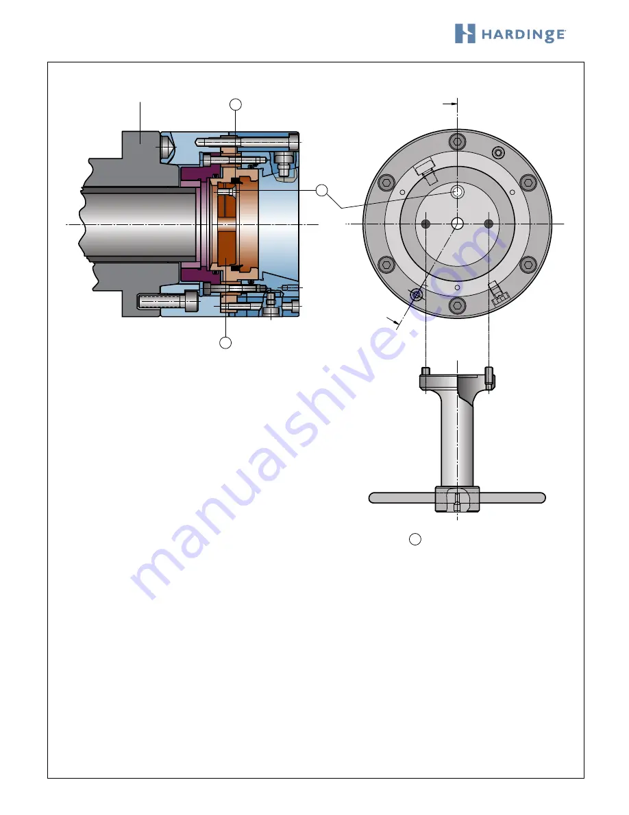
10 PART STOP WRENCH
Removing or Changing the Work Stop
Follow the previous instructions to remove the collet head
before changing the work stop. The collet head must be in
the unclamp position. Reach in and remove the seal #17
and set it aside.
Turn the locking screw #19 counterclockwise to loosen the
threads to allow the removal of the work stop #6. It is not
necessary to remove the locking screw.
A work stop wrench #10 is supplied with the spindle
mount assembly to remove the work stop. Align and insert
the pins of the wrench into the holes in the face of the
work stop. Turn the wrench counterclockwise to unscrew
the work stop. If you feel resistance you must go back and
loosen the locking screw #19.
The work stop has an M12 thread in the center to secure a custom work stop for required workpiece applications.
To reassemble, simply follow the same instructions in reverse order. Insert the work stop with the two pin holes facing out.
Tighten the locking screw by hand to ensure that there will be no movement in the dead-length
®
work stop. Remember to
replace the seal #17 before inserting your collet head. Failure to use the seal may cause malfunction of the collet system.


