CHIP REMOVAL
(Machines without Chip Conveyor)
TALENT
®
6/45 AND 8/52 LATHES
1. Power down and lock out the machine. Refer to
the appropriate power-down procedure in
Chapter 1.
2. If coolant was ON, wait a few minutes to allow
any coolant that was in use to drain back into
the tank.
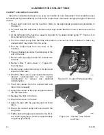
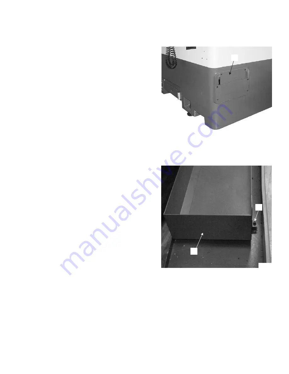
3. Open or remove chip tray cover “C”, Figure 4.3.
- WARNING -
Do not remove chips with your bare
hands.
4. Rake the chips into a suitable container.
5. Close or replace chip tray cover “C”.
TALENT 8/66 AND 10/78 LATHES
1. Power down and lock out the machine. Refer to
the appropriate power-down procedure in
Chapter 1.
2. If coolant was ON, wait a few minutes to allow
any coolant that was in use to drain back into
the tank.
3. Roll the coolant tank from the front of the
machine.
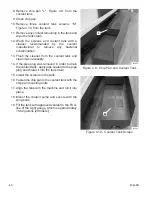
4. Remove two mounting bolts "D", Figure 4.4.
- WARNING -
Do not remove chips with your bare
hands.
5. Rake the chips from chip pan "E" into a suitable
container.
6. Align the tank with the machine and roll it into
place.
M-448B
4-5
Figure 4.3 - Chip Tray Cover
C
TP5248
Figure 4.4 - Chip Pan Mounting Bolt
and Chip Pan
D
E
TP6030
Summary of Contents for Talent 10/78
Page 9: ... NOTES M 448B vii ...
Page 10: ... NOTES viii M 448B ...
Page 17: ... NOTES M 448B 1 7 ...
Page 18: ... NOTES 1 8 M 448B ...
Page 27: ... NOTES M 448B 2 9 ...
Page 28: ... NOTES 2 10 M 448B ...
Page 32: ... NOTES 3 4 M 448B ...
Page 43: ... NOTES M 448B 4 11 ...
Page 44: ... NOTES 4 12 M 448B ...
Page 49: ... NOTES M 448B 5 5 ...
Page 50: ... NOTES 5 6 M 448B ...
Page 61: ... NOTES M 448B 6 11 ...
Page 62: ... NOTES 6 12 M 448B ...
Page 65: ... NOTES M 448B A1 3 ...
Page 66: ... NOTES A1 4 M 448B ...
Page 68: ...A2 2 M 448B Figure A2 3 Coolant Pump Electrical Connection TALENT 6 45 and 8 52 Lathes TP6027 ...
Page 73: ...M 448B A2 7 Figure A2 10 Tailstock Quill Hydraulic Valves TALENT 8 66 and 10 78 Lathes TP6040 ...
Page 78: ...A2 12 M 448B Figure A2 16 Tailstock Hydraulic Valves TALENT 6 45 and 8 52 Lathes TP5240 ...
Page 79: ...M 448B A2 13 Figure A2 17 Tailstock Hydraulic Valves TALENT 8 66 and 10 78 Lathes TP6045 ...
Page 86: ...A2 20 M 448B Figure A2 24 Internal Power Case View Relay Panel TP5208A ...
Page 91: ...M 448B A2 25 Figure A2 29 Internal Power Case View Service Entrance to Power Case TP5217A ...
Page 92: ...A2 26 M 448B Figure A2 30 Internal Power Case View Fuse and Contactor Panel TP5209A ...
Page 97: ...M 448B A2 31 Figure A2 35 Pump for Through Tool Coolant TP5231 ...
Page 98: ...A2 32 M 448B Figure A2 36 Spindle with Chuck Removed TP5236 ...
Page 99: ...M 448B A2 33 Figure A2 37 Spindle with Chuck Installed TP5243 ...
Page 100: ...A2 34 M 448B Figure A2 38 Tailstock Assembly TALENT 6 45 6 45SV 8 52 and 8 52SV Lathes TP5754 ...
Page 101: ...M 448B A2 35 Figure A2 39 Tailstock Assembly TALENT 8 66 and 10 78 Lathes TP6044 ...
Page 102: ...A2 36 M 448B Figure A2 40 Z Axis Drive Motor TALENT 8 66 and 10 78 Lathes TP6049 ...
Page 103: ... NOTES M 448B A2 37 ...


