Page | 17
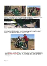
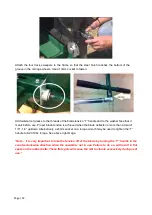
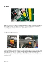
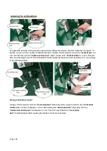
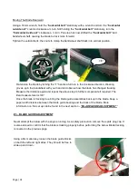
Insert vertical post assemblies into corresponding locations in head assembly and insert the rear square
frame into the carriage base until it hits the bottom as shown in pictures above.
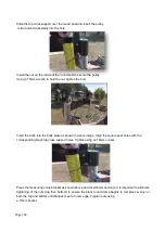
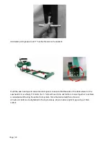
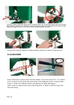
Lock the cam handles on both the round and square post to prevent the head from moving when it is
stood up in the coming steps. Ensure that when activating the cam handles, the clamps securely lock on
the round and square vertical post. If they don
’t, a 13mm wrench will need to be used to tighten the
adjustment nut. This will allow the clamps to lock on the post better.
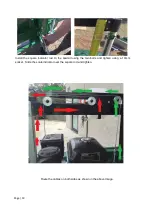
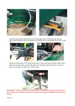
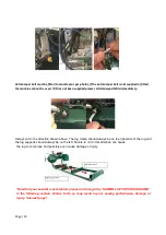
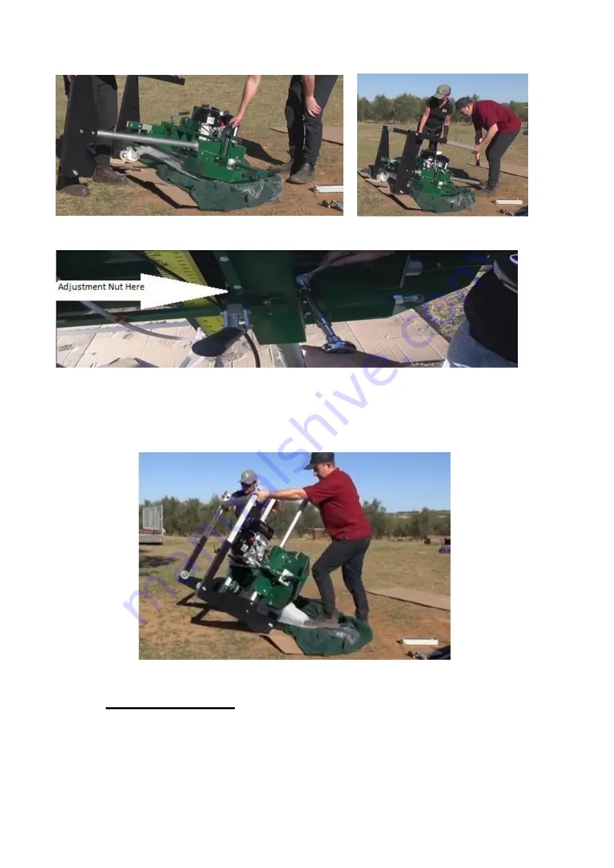
With one person on each post, stand the head assembly up on the wheels as shown above. Again,
using a
minimum of two people
,
set the saw head assembly on the track system ensuring the
carriage wheel grooves rest on the
“L” rails. The square vertical post should be on the same side as
the log supports.
Summary of Contents for GT26
Page 39: ...Page 39 DIAGRAM ...
Page 40: ...Page 40 DIAGRAM ...
Page 41: ...Page 41 DIAGRAM ...
Page 42: ...Page 42 DIAGRAM ...
Page 43: ...Page 43 DIAGRAM ...
Page 44: ...Page 44 NOTES ...
Page 45: ...Page 45 ...


