III
HARGASSNER Heating technology for
Biomass
A 4952 Weng OÖ Tel.: +43/7723/5274-0 Fax: +43/7723/5274-5 office@hargassner.at
11
Operation
Chapter III: Operation
1
Overview of components
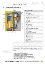
The boiler consists of the combustion chamber and the heat exchanger, and
controls the combustion air with the exhaust fan.
The lambda sensor consistently monitors the flue gases. The integrated sensors
monitor the temperatures of the boiler and the flue gas. The turbulators clean the
heat exchanger through a rod. The boiler cleans itself at regular intervals using
the de-ash system. The ash extraction auger transports the fly ash and the grate
ash into the ash box. The ignition of the pellets takes place through the automatic
Ignition
.
1.1
Function
• Fuel transport from the storage room
• Transport of the fuel into the combustion chamber
• Ignition and combustion of the fuel
• Control of energy transfer to the water based system
• Cleaning of the boiler and the ash extraction into the box
• Evacuation of the flue gases
Pos.
Description
1
Fully refractory-lined combustion chamber
2
Sliding grate
3
Motor for sliding grate
4
Secondary air stream with inlet openings
5
High-temperature insulation plates
6
Primary air
7
Ash box
8
Ignition
9
Stoker auger
10
Circulation zone
11
Heat exchanger
12
Turbulators
13
Automatic heat exchanger cleaning
14
Exhaust fan
15
Full insulation
16
Wood pellet vacuum turbine
17
Pellet-tubes
18
Fuel indicator
19
Pellet day hopper
20
Double rotary valve
21
Drive unit
22
Lambda sensor
1
2
3
4
5
6
7
8
9
10
11
12
13
14
15
16
17
18 19
20
21
Summary of Contents for Classic 12
Page 64: ......


