III
HARGASSNER Heating technology for
Biomass
A 4952 Weng OÖ Tel.: +43/7723/5274-0 Fax: +43/7723/5274-5 office@hargassner.at
39
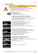
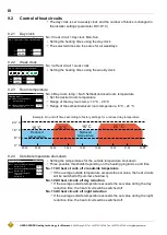
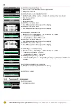
No. A3 Minimum limit for heat circuit 1 flow temperature
This flow temperature won't be underrun in heating or reduction mode
Range: 1 - 80 °C
No. A4 Maximum limit for heat circuit 1 flow temperature
This flow temperature won't be overrun in heating or reduction mode
Floor heating:
Integrate an additional electromechanical thermostat which
interrupts the power supply to the relevant heat circuit pump
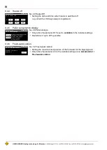
No. A5 Numerical input of the actual value (see mixer type plate)
Duration from closed to open condition
Range: 10 - 300 Sec.
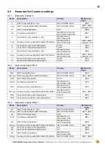
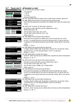
No. A6 Heat circuit
1
and
2
remote control
,
5 setting options:
• non-existent
• Heat circuit with analogue remote control FR25
• Heat circuit with digital remote control FR35
• Heat circuit with digital remote control FR40
• External switch contact
No. A6a / b / c The remote control may be installed with or without a room sensor
• Heat circuit with analogue remote control
FR25 without room sensor
• No automatic adjustment of the room temperature
• Wire FR25 at
terminals 1 and 3
.
• Heat circuit with analogue remote control
FR25 with room sensor
• Automatic adjustment of the room temperature
• Wire FR25 at
terminals 1 and 2
.
• Heat circuit with digital remote control
FR35
or
FR40
If
FR35
is set, parameter
A6b
appears
• If
FR40
is set, parameter
A6c
appears
• If
FR40
is set, parameter
A6c
appears
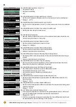
No. A6e Pump switches off after room temperature is exceeded
•
Not activated
: Standard heat circuit control
•
Activated
: If the room temperature (set temperature) is exceeded by the set
value (No. M6 service parameter), the heat circuit pump switches
Off
and the
mixer is
Closed
Pump and mixer switch
On
again when the room temperature drops below
the set room temperature by the preset value (service parameter M6a).
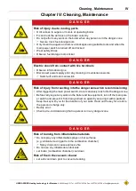
No. A7 Activate district line pump when heat circuit pump 1 is running
No. A8 Activation of summer heating function of the corresponding heat circuit
Heat circuit will be switched on (depending on timer settings) if accumulator is
on temperature
Is only activated in menu
HWT
If
On
is selected, parameters
A8a - A8c
appear
HARGASSNER
Mo,25.11.18 08:19
Minimum flow temperature
Default: 30 °C
No. A3 Heat circuit 1
30°C
HARGASSNER
Mo,25.11.18 08:19
Maximum flow temperature
Default: 70 °C
No. A4 Heat circuit 1
70°C
HARGASSNER
Mo,25.11.18 08:19
Mixer runtime
Default: 90 seconds
No. A5 Heat circuit 1
90 Sec
HARGASSNER
Mo,25.11.18 08:19
non-existent
FR25 (analogue)
FR35 (digital)
FR40 (digital)
Ext. contact
No. A6 Remote control
HARGASSNER
Mo,25.11.18 08:19
with room sensor
without room sensor
No. A6a Heat circuit 1 Remote control
HARGASSNER
Mo,25.11.18 08:19
HWT A
HWT 1
HWT 2
HWT 3
AT
No. A6b Heat circuit 1 Display remote
control
HARGASSNER
Mo,25.11.18 08:19
HCA
No. A6c Heat circuit 1 Display remote
HC1
HC2
HC3
HC4
HC5
HC6
HWT A
HWT 1
HWT 2
HWT 3
AT
Faults
Extr. Heat.
Distr. Heat.
Ext. HC 1
Ext. HC2
Ext. HC3
Warning
Diff
HARGASSNER
Mo,25.11.18 08:19
not activated
activated
No. A6e Heating circuit 1 Pump switches off
after room temperature is exceeded
HARGASSNER
Mo,25.11.18 08:19
no district heating
with district line 1
Controlled district line
No. A7 Heat circ. 1 - Distr. heat pump
HARGASSNER
Mo,25.11.18 08:19
Summer-Heating OFF
Summer-Heating ON
Summer Bath Auto
No. A8 Heating circuit 1 Summer
heating
Summary of Contents for Classic 12
Page 64: ......

