background image

9

Radial Winch 

40.2 ST EL

Installation and Maintenance Manual - Mod.E

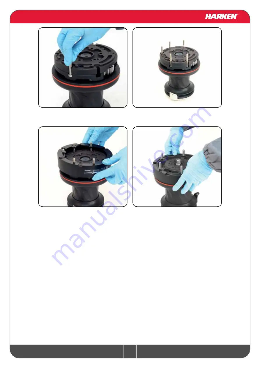
3. Position the 5 M6 hexagonal headed bolts 

in their holes

4. Reposition the skirt n°2 in its housing

5. Press down the skirt to position it correctly

NOTICE

Make sure the skirt is correctly clipped on to the base of the winch. 

Install the winch on the deck in the position you have chosen, keeping in mind the limits described 
on page 6 and using hexagonal headed bolts.

Summary of Contents for 40.2 ST EL Series

Page 1: ...Installation and Maintenance Manual MRW E Powered Radial Winch 40 2 ST EL...

Page 2: ...14 Washing 14 Maintenance table 14 Disassembly procedure 14 Exploded view with maintenance products 18 Assembly 19 Harken limited worldwide warranty 20 Ordering spare parts 20 Exploded view 21 Radial...

Page 3: ...e operations described in this Manual NOTICE To use and understand this manual user must refer to other documents available on web site www harken com and listed below The Dual Funtion Control Box use...

Page 4: ...in chrome bronze CW chrome white BBB all bronze CCC All Chrome bronze EH horizontal electric winch Maximum working load WARNING The maximum working load MWL for the 40 2 ST Radial Winch is 850 Kg 1874...

Page 5: ...Radial Winch 40 2 ST EL Installation and Maintenance Manual Mod E Outline Winch 40 2 ST EL Horizontal electric motor 12 V 24 V 175 80 5 82 156 Line entry height 175 80 5 82 156 155 43 Line entry heigh...

Page 6: ...th can result in the winch pulling off the deck suddenly and unexpectedly during high loads causing severe injury or death WARNING Verify the entry angle of the sheet This must be 8 with tolerance of...

Page 7: ...he drum and use Socket Head SH bolts Tools needed One medium flat bladed screwdriver To identify the various parts refer to the exploded view at the end of this Manual Torque to apply when assembling...

Page 8: ...k in the position you have chosen keeping in mind the limits described on page 6 and using socket head SH bolts Procedure 2 not pertinent for ST BBB CCC versions To install the winch remove the winch...

Page 9: ...ir holes 4 Reposition the skirt n 2 in its housing 5 Press down the skirt to position it correctly NOTICE Make sure the skirt is correctly clipped on to the base of the winch Install the winch on the...

Page 10: ...mm and a 80 mm diameter holes C Bolt the base of the winch to the deck using five M6 bolts not supplied by Harken as described at Procedure 1 or Procedure 2 correctly chosen for the thickness and type...

Page 11: ...ing or carrying out maintenance on the winch Once you have installed the winch on the deck proceed with motor installation The motor can be coupled to the winch in different positions Check the space...

Page 12: ...refer to the Dual Function Control Box manual WARNING Before installing and using the device read carefully the Dual Function Control Box manual available on web site www harken com Refer to the follo...

Page 13: ...or using a spanner and tighten other nut with second spanner Take special care not to turn the central spindles These instructions apply when assembling and disassembling We recommend using a torque w...

Page 14: ...ng or racing In addition they must be completely overhauled cleaned and lubricated at least every 12 months After an inspection replace worn or damaged components Do not replace or modify any part of...

Page 15: ...inside the drum support 10 Remove the washer n 12 11 Remove the gear n 7 8 Unscrew the 6 hex screws n 16 8Nm 70 in lb 7 Slide out the central shaft n 19 6 Completely unscrew the three screws n 27 and...

Page 16: ...40 2 ST EL Installation and Maintenance Manual Mod E 15 Remove the gear n 10 16 Remove the pawls carrier n 11 17 Remove the washer n 9 13 Remove the gear n 3 14 Remove the gear n 14 12 Remove the paw...

Page 17: ...hat do not leave residue Inspect gears bearings pins and pawls for any signs of wear or corrosion Carefully check the teeth of gears and ring gears to make sure there are no traces of wear Check the r...

Page 18: ...ent that must be greased apply Harken grease with a brush in a proper quantity as shown below Harken Grease G Harken Pawl Oil O Anti seize A G A A A G G G G G G O O G G A G 1 G 2 Exploded view with ma...

Page 19: ...rken Tech Service techservice harken it If the jaws have been disassembled insert peeler between the two jaws taking care that the letters TOP on the peeler are facing upwards When positioning the str...

Page 20: ...he winch is printed on a plate on the drum support of the winch W XXXXX XXXXXXXXX Harken limited worldwide warranty Ordering spare parts Headquarters Harken Inc 1251 East Wisconsin Avenue Pewaukee Wis...

Page 21: ...21 Radial Winch 40 2 ST EL Installation and Maintenance Manual Mod E Exploded view 20 16 15 17 18 23 22 24 25 21 26 27 28 29 Exploded view Radial Winch 40 2 STA STC STCW EL...

Page 22: ...22 Radial Winch 40 2 ST EL Installation and Maintenance Manual Mod E 2 1 14 13 9 10 5 6 11 8 3 4 6 5 7 12 20 19 30 Radial Winch 40 2 STA STC STCW EL...

Page 23: ...S414900080 Assy Gear Z20 Gear Z20 Bushing 12x 14x8 15 1 2 1 A94141500 S414890080 S4130900A7 Assy Housing Winch 40 Support W40 Bushing 9x 11x7 Bushing 22x 25x8 5 16 6 M0635103 Socket head screw M6x16...

Page 24: ...14900080 Assy Gear Z20 Gear Z20 Bushing 12x 14x8 15 1 2 1 A94141500 S414890080 S4130900A7 Assy Housing Winch 40 Support W40 Bushing 9x 11x7 Bushing 22x 25x8 5 16 6 M0635103 Socket head screw M6x16 UNI...

Page 25: ...ear Z20 Gear Z20 Bushing 12x 14x8 15 1 2 1 A94141500 S414890080 S4130900A7 Assy Housing Winch 40 Housing W40 Bushing 9x 11x7 Bushing 22x 25x8 5 16 6 M0635103 Socket head screw M6x16 UNI5931 Pos Q ty C...

Page 26: ...26 Radial Winch 40 2 ST EL Installation and Maintenance Manual Mod E 19 15 14 16 17 29 21 23 24 20 25 26 27 28 Radial Winch 40 2 STBBB STCCC EL...

Page 27: ...27 Radial Winch 40 2 ST EL Installation and Maintenance Manual Mod E 1 13 12 8 9 4 5 10 7 2 3 5 4 6 11 19 18 30 Radial Winch 40 2 STBBB STCCC EL...

Page 28: ...ng Winch 40 Support W40 Bushing 9x 11x7 Bushing 22x 25x8 5 15 6 M0635103 Socket head screw M6x16 UNI5931 16 1 S413150082 Washer 62x 80x1 5 17 2 A74136000 Bearing 56x 68x24 Pos Q ty Code Description 18...

Page 29: ...0 Support W40 Bushing 9x 11x7 Bushing 22x 25x8 5 15 6 M0635103 Socket head screw M6x16 UNI5931 16 1 S413150082 Washer 62x 80x1 5 17 2 A74136000 Bearing 56x 68x24 Pos Q ty Code Description 18 1 1 A9414...

Page 30: ...31 3 1 8 8 1 1 A94149500 S415360003 M601560097 M6007297 M0612097 KIT EL HO Motor Flange Horizontal Motorgear Flange Screw M6x16 UNI EN ISO 5931 2003 precote coating O Ring Seal ORM 0055 10 5 5 x 1 Lip...

Reviews: