background image


MKIV Ocean Unit 3 

24

Commissioning Pendant/Halyard: Restrainer/Tension

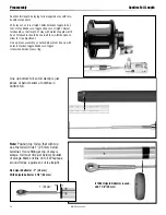
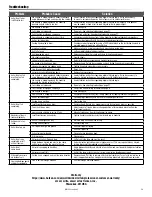
Halyard Deflector/Halyard Restrainer

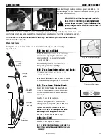
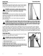
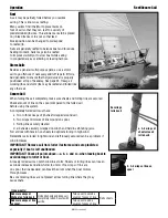
To prevent wraps, jib halyard must pull slightly to rear. On most boats, 

halyard lead angle is acceptable if halyard swivel is raised to top of foil.
On some boats halyard sheaves are located too close to headstay and  

a Halyard Deflector or Halyard Restrainer must be used.
Halyard restrainers should be used only when required by masthead 

geometry. Restrainers tend to limit sail luff length and may cause  

problems if not installed properly.
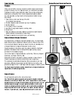
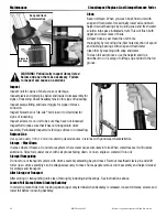
If your boat needs a Halyard Deflector, use Part No. 7304 or a Halyard 

Restrainer, use Harken Part No. 945.
Restrainer should be mounted as high as possible on face of mast. 

Position restrainer so that foils will not hit it when under load.
The restrainer should deflect halyard as little as possible or you may  

experience difficulty in tensioning sail luff, friction when furling, and  

possible damage to foils. To decrease deflection angles, shorten sail luff.

Tip: Boats used in charter service should have a halyard restrainer, 

regardless of masthead geometry.

Halyard Tension

The jib halyard should be firm, but not too tight.

Tip: The luff foil system supports sail along its length so halyard  

tension is used only to shape sails, not to support them. Use enough 

halyard tension to remove some wrinkles along luff of sail. Do not 

tension halyard enough to cause vertical wrinkles in luff of sail. 

Tension to adjust position of draft in sail to suit sailing conditions. 

Halyard should be firm but not tight. If in doubt, release halyard  

tension. To protect sail, ease halyard when boat is not in use.

Pendants

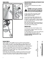
If the your sail luff is not long enough to position halyard swivel high 

enough to create an 8–10° angle as shown, you must add a pendant. 

Pendants should be made of plastic-coated wire and be permanently 

attached so sail height will be correct. Adjustable-length pendants  

are not acceptable, as they might not be adjusted correctly during a  

sail change.
1. Raise sail so sail is near the top of the foil. 

    Do not attach tack shackle. 

2. Position halyard swivel correctly near top of headstay.  

3. Secure halyard. 

4. Tie a piece of rope to sail tack. 

5. Lead line through tack shackle on furling drum. 

6. Tension sail. 

7. Measure distance from tack shackle to sail tack and permanently 

  attach pendant of this length to head of sail. 

8. Repeat procedure for every jib in your sail inventory.

Halyard Deflector

Halyard Restrainer

Summary of Contents for 7513.10

Page 1: ...Tools 5 Dimensions Sailmaker s Instructions 6 Toggle Deductions Stay Into Foil Options 7 Top Foil Length 8 Short Top Foil 9 Confirm Foil Length 10 Assembly Foils Connectors 11 14 Halyard Swivel and Drum Assembly 15 Rod Rigging 16 Turnbuckle Toggle 17 19 Final Feeder 20 Commissioning Turnbuckle 21 Lead Line to Cockpit 22 Halyard Wrap Prevent Halyard Wrap 23 Pendant Halyard Restrainer Halyard Tensio...
Page 2: ... damage or harm caused by not observing the safety requirements and instructions in this manual See limited warranty general warnings and instructions in www harken com en general warnings instructions Purpose Harken Jib Reefing and Furling is designed for rolling sails on sailboats to reduce sail size or to completely roll so wind has little effect on the sail Use of this product for other than n...

Page 3: ...nplate Clevis Pin Size 7413 20 3 4 Jaw jaw toggle w short link plate 3 4 19 1 mm 7413 20 7 8 Jaw jaw toggle w short link plate 7 8 22 2 mm 7513 20 1 Jaw jaw toggle w short link plate 1 25 4 mm 7513 20 1 1 8 Jaw jaw toggle w short link plate 1 1 8 28 6 mm 7313 21 3 4 Long link plate w jaw jaw toggle 3 4 19 1 mm 7313 21 7 8 Long link plate w jaw jaw toggle 7 8 22 2 mm 7513 21 1 Long link plate w jaw...

Page 4: ...513 31F 10 7 177 8 mm Connectors HFG1017 1 Connector bushing set Includes 10 H 84186 Bushing connector half top 10 H 84187 Bushing connector half bottom HFG1011 1 Foil screw set Includes 44 HFS1060 Foil screws extras included HFG1012 1 Trim cap set Includes 1 H 84231 Trim cap half top 1 H 84232 Trim cap half bottom 3 HFS1127 Trim cap screws includes one extra HFG1013 1 Feeder set Includes 2 H 8424...

Page 5: ...rigging requires Harken rod adapter stud Toggles Furling line is not included with furling unit Purchase 12 mm 7 16 low stretch polyester double braid line Line length should be equal to the length of the boat plus the length of the foot of the largest genoa plus 2 m 6 Line Diameter Length WARNING A stay that is old or damaged can break suddenly causing an accident Headstay condition should be che...

Page 6: ...he way Do not add to halyard swivel or top terminal dimensions 3 4 19 9 mm Clevis pin Add 16 5 8 to 7 3 4 422 mm to 197 mm 7 8 22 2 mm Clevis pin Add 16 5 8 to 7 3 4 422 mm to 197 mm Note These additions are determined by subtracing the short link plate assemblies from the length of the long link plate assembly 1 25 4 mm Clevis pin Add 16 1 2 420 mm 1 1 8 28 6 mm Clevis pin Add 16 1 2 420 mm A B L...

Page 7: ...od adapter nosepiece for Harken rod adapter stud WARNING Using a threaded nosepiece with only adhesive at the upper rod eye terminal may result in headstay system failure which can cause an accident damage to your vessel personal injury or death See www harken com for additional safety information STA LOK is a registered trademark of STA LOK Terminals Ltd Unit Clevis pin Ø Pin to pin length 3 3 4 ...

Page 8: ...measurement Length Check G Toggle Distance from Lower Clevis Pin to Crosspin Hole Toggle Part No Type Clevis Pin G Distance 7413 20 3 4 Jaw jaw with short link plate 3 4 19 1 mm 5 42 138 mm 7313 20 7 8 Jaw jaw with short link plate 7 8 22 2 mm 6 00 152 mm 7513 20 1 Jaw jaw with short link plate 1 25 4 mm 6 79 173 mm 7513 20 1 1 8 Jaw jaw with short link plate 1 1 8 28 6 mm 7 24 184 mm 7313 21 3 4 ...

Page 9: ...n above Unit 3 Top foil length from worksheet 5 1 2 11 2 140 38 mm Actual Top Foil 6 1 2 165 mm Do not cut top foil to length from worksheet Cut top foil to 6 1 2 165 mm and shorten trim cap by 1 3 8 35 mm as shown at left Shorten bottom foil per chart below Foil will be clamped in upper holes 7 7 8 200 mm Cut 1 3 8 35 mm off top trim cap Cut off Do not use 6 1 2 165 mm UNIT 3 Top foil length from...

Page 10: ...ht No halyard deflector 1 25 mm With halyard deflector 2 1 8 54 mm If 7304 Halyard Deflector is used add 1 1 8 29 mm 1 25 mm Confirm foil length by laying foils alongside stay with turn buckle components Pull stay out so it is straight Attach Harken toggle to bot tom of stay Make sure toggle straps are straight Adjust turnbuckle so that length of stay with Harken toggle will fit boat Turnbuckle sh...

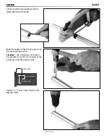
Page 11: ...sing rat tail file Drill two 1 8 3 mm holes in foil for self tapping screws Mark the location of the trim cap screws at the cut end of the top foil Location 1 25 4 mm down from top of foil and 9 16 14 2 mm from center of the sail groove See dimensions below 1 25 4 mm 9 16 14 2 mm 1 1 8 28 5 mm ...

Page 12: ...or faster assembly Over a marine eye located on the bottom of the stay From the top if lower terminal is part of turnbuckle Check fit of marine eye before proceeding This will generally work with smaller wires within the unit s rigging specifications Place halves of trim cap over wire and insert into top foil Use a small hammer to tap in place if necessary Tip With foil groove up have screw holes ...

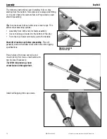
Page 13: ... used Red Loctite Halyard Deflector Put a drop of red Loctite in screw holes Place connector on wire with hooked side up Red Loctite in screw holes Hooked side of connector Use a hex key wrench to securely tighten screws Loctite is a trademark of Henkel AG Company KGaA ...

Page 14: ...nector and mating with four recesses in bottom part of bushing Put a drop of red Loctite into screw holes Red Loctite in screw holes Slide foil completely over bushings and connector Use a hex key wrench to securely tighten screws Continue assembly of foil system Loctite is a trademark of Henkel AG Company KGaA ...

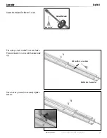
Page 15: ...MKIV Ocean Unit 3 15 Assembly Halyard Swivel Drum Assembly Slide halyard swivel onto foil IMPORTANT Make sure up arrow is up Slide drum assembly onto foil ...

Page 16: ... Apply a few drops of red Loctite to threads of nosepiece Screw main threaded stud portion onto bronze nosepiece until flats align with two cotter pin holes in terminal body Tip Turn nosepiece completely into threaded stud portion Flats will be close and may only require a small half turn to align with cotter pin holes R O D R I G G I N G R O D R I G G I N G Loctite is a trademark of Henkel AG Com...

Page 17: ...hown below Connect eye to toggle jaw using special clevis pin Secure using cotter pin If stay length is set use side cutters or needle nose pliers to bend cotter pin to secure turnbuckle Make sure shallow jaw is up Up Down STA LOK is a registered trademark of Barfield Engineering Company Ltd Assembly Attach Turnbuckle Toggle ...

Page 18: ...gle Recess turnbuckle into drum assembly slip link plates over special clevis pin and secure using fasteners Use blue Loctite adhesive on screws Secure to toggle using lock nuts Apply isolator Loctite is a registered trademark of Henkel AG Company KGaA ...

Page 19: ...ocknuts Determine height of link plates to provide anchor clearance and cut to length Cut at scribe mark Deburr edges Connect eye to toggle jaw using special clevis pin Secure using cotter pin Toggle For Long Link Plates Blue Loctite WARNING Stay must attach to toggle Do not attach stay to crosspin at drum assembly because crosspin and plates may fatigue and break Stay attached to toggle Loctite i...

Page 20: ...nce system is up on the mast and turnbuckle adjusted Blue Loctite in screw holes Lift foils so top of foils ride about 1 25 mm below upper terminal Slide halyard swivel above feeder Place feeder tabs in position Use a drop of 833 Blue Loctite in screw holes Use hex key wrench to secure Loctite is a trademark of Henkel AG Company KGaA ...

Page 21: ...to lift and hold it about 1 5 m 5 Raise foils using second halyard and secure Allow room above for turnbuckle take up Adjust turnbuckle Replace used cotter pins and locknuts Lower drum assembly and install clevis pin and new cotter pin Lift foils so top is 25 mm 1 below upper terminal WARNING Make sure drum assembly and foils are securely lifted with a halyard before adjusting turn buckle Foils ca...

Page 22: ...n opposite direction Lead line to furling line cleat in cockpit 2670 75 mm Carbo Ratchet Block Install so line is angled as shown Furling Line Cleat Furling line lead changes as amount of furling line on drum changes Furling line must enter drum at right angle to headstay 2600 Carbo intermediate lead block 2600 Carbo intermediate lead block 2670 Carbo Ratchet block Stern BOW 2660 Carbo forward lea...

Page 23: ...there has been a halyard wrap so they can avoid an accident by relying on standing rigging or halyards Inspection must be done while rigger is suspended from a separate crane or mast must be lowered to perform inspection Some professionals may rig a new line through internal masthead sheaves to serve as a temporary headstay to hold mast in place Wire rod rigging terminals toggles clevis pins or co...

Page 24: ... halyard should be firm but not too tight Tip The luff foil system supports sail along its length so halyard tension is used only to shape sails not to support them Use enough halyard tension to remove some wrinkles along luff of sail Do not tension halyard enough to cause vertical wrinkles in luff of sail Tension to adjust position of draft in sail to suit sailing conditions Halyard should be fir...

Page 25: ... not be possible to attach spinnaker halyard to bow pulpit or it may be sucked into jib when furling On some boats the spinnaker halyard lays across headstay and will catch on halyard swivel foils or jib halyard To prevent problems it may be necessary to install a masthead bail to move spinnaker halyard block forward and to one side Boats with external halyards may find it necessary to flip both e...

Page 26: ...at the dock See Furl and Unroll Sail 11 If not sailing right away make sure sail is furled carefully See Secure Sail WARNING Sail can become uncontrollable when raising in windy conditions resulting in loss of footing Choose wind conditions to match your experience and ability If changing sails underway take all safety precautions when working on the foredeck See www harken com manuals General War...

Page 27: ...ight wind and left loosely secured can be a problem if wind increases IMPORTANT Remove sail from furler if extreme winds are predicted especially if boat is left unattended IMPORTANT Check all points above a b c and d when leaving boat to avoid damage to furler or boat A loosely rolled sail can catch wind in a storm Sheets or furling lines can loosen as winds increase and allow furler to unroll If...

Page 28: ...ly to mast Some people remove drum assembly and halyard swivel for storage and transport After Storage or Transport After storing or transporting unit clean thoroughly including ball bearings See instructions above Loosen Foil Clamp Before Slacking Backstay In order to prevent foils from locking against upper stay terminal when backstay is released loosen foil clamp screws and lower foil before lo...

Page 29: ...ptimal halyard angle Foils riding on turnbuckle Raise foils See adjusting turnbuckle on page 21 Foils too high binding on swage eye Lower foils See adjusting turnbuckle on page 21 Jib halyard is too tight Ease jib halyard Spare halyard is wrapping in sail as it furls Secure spare halyards away from furling headstay by flipping them behind spreaders Salt or dirt in bearings Flush bearings frequentl...

Page 30: ...ont de Nemours and Company or its affiliates Loctite is a trademark of Henkel AG Company KGaA 3 7312 21 5 8 7312 21 3 4 8 2 6 8 8 6 2 5 8 7 1 4 7 3 9 5 No Description Order Part No Part No Part No Part No Long Link Plate w Toggle 7313 21 3 4 7313 21 7 8 7513 21 1 7513 21 1 1 8 1 Toggle 1 H 41489 H 42562 7513 20 1 7513 20 1 1 8 2 Strap 2 H 42568 H 42568 H 84078 H 84078 3 Cross Pin 1 H 42583 H 42584...

Page 31: ... MP 128 7 6 7 1 2 3 6 Connector w Bushings and Foil Screws 1 7513 31 4 Connector 1 7513 31F 5 Connector Bushing top half shorter 1 H 84186 6 Connector Bushing bottom longer w hook 1 H 84187 7 Foil Screw 4 HFS1060 HFG997 9 IMPORTANT Ball bearings are not self contained Remove halyard swivel to change balls or use shaving cream to hold balls in place Use a catch box taped below Please read these ins...

Page 32: ...n it Email info harken it Harken New Zealand Ltd 129 Westhaven Drive Westhaven Auckland 1011 New Zealand Telephone 64 9 303 3744 Fax 64 9 307 7987 Web harken co nz Email harken harken co nz Harken Polska SP ZOO ul Rydygiera 8 budynek 3A lokal 101 I piętro 01 793 Warszawa Poland Tel 48 22 561 93 93 Fax 48 22 839 22 75 Web harken pl Email polska harken pl Harken Sweden AB Main Office and Harken Bran...

Reviews: