background image

7

Performa

 Winch 

50.2 STP EL/HY

Installation and Maintenance Manual - Mod.D

Procedure

To install the winch, remove the drum and use Socket Head (SH) bolts.

Tools needed

   One medium flat-bladed screwdriver

To identify the various parts, refer to the exploded view at the end of this Manual.

 Torque to apply when assembling 

Install the winch on the deck in the position you have chosen, keeping in mind the limits described 
on page 4 and using socket head (SH) bolts. 

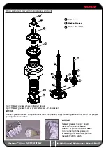
1. Pull out the disconnect rod n°30

3.  Slide off the assy socket n°29 and the cover 

n°28. Pay attention to the o-ring in the socket.

5.  Remove the stripper arm n°26 by 

rotating and lifting it.

6. Lift off the drum n°23

2. Unscrew the central screw ( 2Nm/18 in-lb)

4.  Unscrew the three screws n°27          

( 4Nm/35 in-lb)

Summary of Contents for Powered Performa Winch 50.2 STP EL

Page 1: ...Powered Performa Winch 50 2 STP EL HY Installation and Maintenance Manual MRPW D...

Page 2: ...e self tailing arm 9 Motor installation procedure 9 Electric equipment 10 Hydraulic connections diagram 13 Maintenance 14 Washing 14 Maintenance table 14 Winch disassembly procedure 14 Winch exploded...

Page 3: ...he theoretical power ratio does not take friction into account Performance data Winch 50 2 STP EL electric horizontal motor vertical motor 12 V 1500 W 24 V 2000 W 12 V 1500 W 24 V 2000 W 1st speed 2nd...

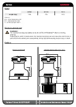
Page 4: ...lectric winch H vertical hydraulic winch Maximum working load WARNING The maximum working load MWL for the 50 2 ST EL HY Performa Winch is 1450 Kg 3197 lb Subjecting the winch to loads above the maxim...

Page 5: ...2 STP EL HY Installation and Maintenance Manual Mod D 195 212 111 96 140 394 195 111 96 130 Vertical electric motor 12 V 24 V Hydraulic motor 195 212 111 96 140 195 212 111 96 233 130 Line entry heigh...

Page 6: ...f mounting fasteners or failure to ensure the correct deck strength can result in the winch pulling off the deck suddenly and unexpectedly during high loads causing severe injury or death WARNING Veri...

Page 7: ...anual Torque to apply when assembling Install the winch on the deck in the position you have chosen keeping in mind the limits described on page 4 and using socket head SH bolts 1 Pull out the disconn...

Page 8: ...ket Head SH bolts no supplied by Harken correctly chosen for the thickness and type of the boat deck Consult the yard that built the boat in case of doubt WARNING To install the winch on the deck use...

Page 9: ...nance on the winch Once you have installed the winch on the deck proceed with motor installation The motor can be coupled to the winch in different positions Check the space available below deck and c...

Page 10: ...unction Control Box containing solenoids to bulkhead or wall for all installation details and for all electric wiring schemes refer to the Dual Function Control Box manual WARNING Before installing an...

Page 11: ...motor using a spanner and tighten other nut with second spanner Take special care not to turn the central spindles These instructions apply when assembling and disassembling We recommend using a torqu...

Page 12: ...un The motor also needs a third connection with a low pressure tube for drainage so that excess oil can return to the main tank to avoid shortening the life of the motor This motor uses an open centre...

Page 13: ...the beginning and end of every season of sailing or racing In addition they must be completely overhauled cleaned and lubricated at least every 12 months After an inspection replace worn or damaged c...

Page 14: ...arry out procedure as shown in the paragraph on winch installation and then do the following 7 Completely unscrew the three screws n 27 and remove the stripper arm support n 22 9 Unscrew the 5 hex scr...

Page 15: ...d Maintenance Manual Mod D 13 Remove the gearing n 9 and remove the pawls n 7 To facilitate the operation press the spring against the pawl with a blade 14 Slide off gear n 2 16 Slide off gear n 5 15...

Page 16: ...with cloths that do not leave residue Inspect gears bearings pins and pawls for any signs of wear or corrosion Carefully check the teeth of gears and ring gears to make sure there are no traces of wea...

Page 17: ...y Harken grease where indicated above Apply Harken grease 1 on assy socket screw 2 on washer NOTICE On every gear and every component that must be greased apply Harken grease with a brush in a proper...

Page 18: ...its housing as shown at left Hold the spring closed and slide the pawl into its housing Once in position check that the pawls can be easily opened and closed with a finger NOTICE Before screw the cent...

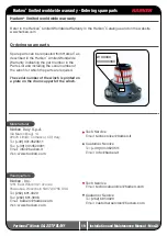
Page 19: ...f the winch is printed on a plate on the drum support of the winch Harken limited worldwide warranty Ordering spare parts Headquarters Harken Inc 1251 East Wisconsin Avenue Pewaukee Wisconsin 53072 37...

Page 20: ...20 Performa Winch 50 2 STP EL HY Installation and Maintenance Manual Mod D Exploded view 1 2 Performa Winch 50 2 STP EL HY 29 28 26 22 25 24 27 23 18 19 18 16 17 21 31...

Page 21: ...21 Performa Winch 50 2 STP EL HY Installation and Maintenance Manual Mod D Exploded view 2 2 Performa Winch 50 2 STP EL HY 21 3 11 12 11 10 8 7 5 4 30 20 13 9 7 8 6 2 1 14 15...

Page 22: ...h 50 Bushing 12x 14x8 Bushing 12x 14x11 Bushing for support 17 5 M0606303 Screw M8x25 UNI 5931 Pos Q ty Code Description 18 2 A74135100 Bearing 85x 97x26 19 1 S413520080 Spacer 20 1 1 A96753100 S41388...

Page 23: ...5931 3 1 1 1 A96010700 A96010600 M6014206 KIT EL Motor 12V 1 5kW KIT EL Motor 24V 2kW Electric Motor Polarity motor sticker Screw stud M6x26 Washer 6 Nut M6 UNI5588 Key DIN 6885 5x5x15 4 1 M0612097 S...

Page 24: ...gear box 1 21 3 Pos Q ty Code Description 3 1 4 4 1 6 6 4 A94150500 M0602903 M0603103 M6007297 M6015697 S415360003 M0606303 KIT EL VT Motor Flange Vertical Motorgear Flange NUT M8 UNI 5588 A4 WASHER 8...

Page 25: ...35303 KIT Clutch HY Motor W46 70 Toothed coupling Connecting Coupling 31 5 Spring pin 5x40 DIN1481 Bushing Spring Washer Screw M8x16 UNI6109 Pos Q ty Code Description 4 1 6 6 1 2 2 A94149100 S41536000...

Reviews: