Fit and align the trim kit by hanging the threaded rods from the slot as Picture 3C.
If the panel is not balanced, move the projector lift either releasing the screws that lock the “L”
brackets to the aluminium profile making them sliding or releasing the screws that anchor the brackets
to the ceiling using the sliding hole milled out of them (max 3 cm. the hole on the ceiling is central).
If the lift does not line up horizontally to the false ceiling, modify the length of the bars or the “CLOSED
STOP POSITION”, following the instructions above described.
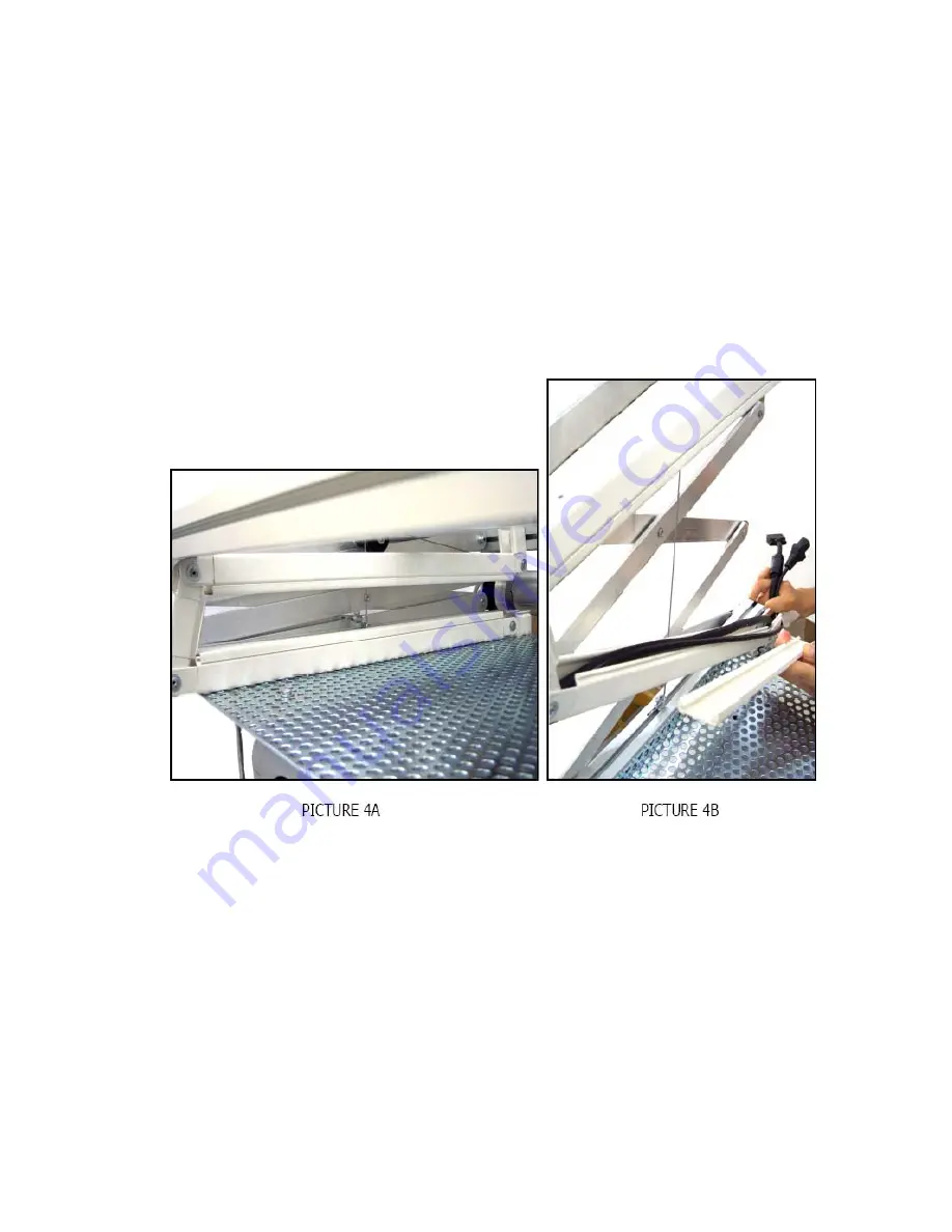
The signal and power cables should run inside the plastic channel supplied. Remove the upper side of
the plastic trunking and place the cables inside as shown below. ( Pictures 4A & 4B )


