background image

8-bit compatible shift / store register

BU4094BC / BU4094BCF / BU4094BCFV

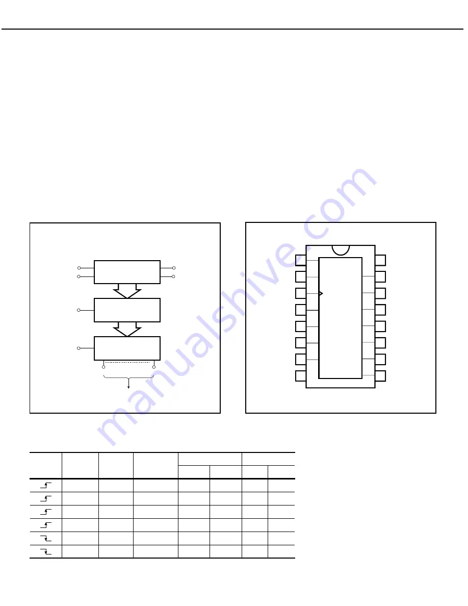
The BU4094BC, BU4094BCF, and BU4094BCFV are shift / store registers, each consisting of an 8-bit register and

an 8-bit latch.

As the data in the shift register can be latched by an asynchronous strobe input, it is possible to hold the output in

the data transfer mode.

The tri-state parallel output can be connected directly with an 8-bit bus line.

These registers are suitable for in-line / parallel data conversion, data receivers and other similar applications.

Logic circuit diagram

Truth table

8-STAGE

SHIFT REGISTER

IN

CLOCK

SERIAL

Q

S

Q'

S

SERIAL
OUTPUT

PARALLEL OUTPUTS

8-BIT

LATCHES

STROBE

3-STATE

OUTPUTS

OUTPUT

ENABLE

Q

1

Q

8

CLOCK

OUTPUT

ENABLE

STROBE

Parallel output

Serial output

Q

1

Q

n

Q

S

H

H

L

L

Q

7

NC

H

H

H

H

Q

7

NC

H

L

X

NC

NC

Q

7

NC

L

X

X

Z

Z

Q

7

NC

H

X

X

NC

NC

NC

Q

S

L

X

X

Z

Z

NC

Q

S

Q

n-1

Q

n-1

SERIAL  IN

Q'

S

NC: No  Change    Z: High  Impedance    X: Irrelevant

Block diagram

2

SERIAL

 IN

STROBE

Q

1

Q

2

Q

3

Q

4

CLOCK

3

4

5

6

7

8

15

14

13

12

11

10

9

V

SS

1

OUTPUT
ENABLE

V

DD

Q

6

Q

7

Q

8

Q'

S

Q

5

Q

S

16

AVR310 


harman/kardon 

85

Summary of Contents for AVR 310

Page 1: ...N HK2001 01 15 SERVICE BULLETIN HK2001 03 17 SERVICE BULLETIN HK2003 02 18 SERVICE BULLETIN HK2003 07 19 TECH TIP HKTT2002 01 21 TECH TIP HKTT2003 01 23 TECH TIP HKTT2004 03 24 IDLE CURRENT TUNER ALIGNMENT 28 UNIT EXPLODED VIEW 29 EXPLODED VIEW PARTS LIST 30 BLOCK DIAGRAMS 31 PCB DRAWINGS 33 ELECTRICAL PARTS LIST 45 SEMICONDUCTOR PINOUTS 66 SCHEMATICS 115 WIRING DIAGRAM 132 PACKAGE 135 harman kard...

Page 2: ...or to applying power to the unit under test 2 After removing an electrical assembly equipped with ES devices place the assembly on a conductive surface such as aluminum foil to prevent electrostatic charge build up or exposure of the assembly 3 Use only a grounded tip soldering iron to solder or unsolder ES devices 4 Use only an anti static solder removal device Some solder removal devices not cla...

Page 3: ...rnate method as follows Plug the power cord directly Into a 120 volt AC receptacle do not use an Isolation Transformer for this test Using two clip leads connect a 1500 ohms 10watt Resistor paralleled by a 0 15uF capacitor in series with all exposed metal cabinet parts and a known earth ground such as a water pipe or conduit Use a VTVM or VOM with 1000 ohms per volt or higher sensitivity to measur...

Page 4: ...tortion 1kHz 50 Mod 0 8 Selectivity 10kHz 30dB Video Section Television Format NTSC Input Level Impedance 1Vp p 75 ohms Output Level Impedance 1Vp p 75 ohms Video Frequency Response 10Hz 8MHz 3dB General Power Requirement AC 120V 60Hz Power Consumption 72W idle 580W maximum 2 channels driven Dimensions Max Width 17 3 inches 440mm Height 6 5 inches 165mm Depth 17 1 inches 435mm Weight 32 lb 14 5 kg...

Page 5: ...trols When the button is pressed so that the words TONE IN appear in the Main Information Display Û the settings of the Bass and Treble controls may be used to adjust the output signals When the button is pressed so that the words TONE OUT appear in the Main Information Display Û the output signal will be flat without any bass or treble alter ation no matter how the actual Bass and Treble controls...

Page 6: ...gi tal recording device See page 30 for informa tion on configuring the Digital Coax 3 Jack to an output Video 4 Input Jacks These audio video jacks may be used for temporary connection to video games or portable audio video products such as camcorders and portable audio players Bass Control Turn this control to modify the low frequency output of the left right chan nels by as much as 10dB Set thi...

Page 7: ...rs light when the Logic 7 mode is in use LOGIC 7C appears for the Cinema version of Logic 7 LOGIC 7M appears for the Music version of Logic 7 See page 26 for a description of the Logic 7 Modes L Hall Mode Indicators These indicators light when one of the Hall modes has been selected M OSD Indicator When the OSD system is in use this indicator lights to remind you that the other indicators in this ...

Page 8: ...ashes when entering presets and other information into the tuner s memory V Stereo Indicator This indicator lights when an FM station is being tuned in stereo W Tuned Indicator This indicator lights when a station is being received with sufficient signal strength to provide acceptable listening quality X Auto Indicator This indicator lights when the tuner s Auto mode is in use Y Main Information D...

Page 9: ...ª fi fl a b c d e A A f g i j FL FR SL SR CENTER SUBWOOFER 31 32 IN OUT IN h k 33 Tape Inputs Tape Outputs Video 1 Audio Inputs AM Antenna Video 1 Audio Outputs DVD Audio Inputs FM Antenna CD Inputs ª 6 Channel Direct Inputs Multiroom Outputs Preamp Outputs Subwoofer Output Video Monitor Outputs Front Speaker Outputs fi Surround Speaker Outputs fl Switched AC Accessory Outlet Unswitched AC Accesso...

Page 10: ...ory Outlet This outlet may be used to power any device you wish to have turned on when the AVR 310 is turned on with the System Power Control switch 2 Unswitched AC Accessory Outlet This outlet may be used to power any AC device The power will remain on at this outlet regard less of whether the AVR 310 is on or off Note The total power consumption of all devices connected to the accessory outlets ...

Page 11: ... Tuner Select h Learn Button i Test Button j Sleep Button k Surround Mode Selector l Night Mode m Channel Select Button n Buttons o Button p Set Button q Digital Select r Numeric Keys s Tuner Mode t Direct Button u Tuning Up Down v OSD Button w Macro Buttons x Transport Controls y Skip Up Down Buttons z Disc Skip Buttons Preset Up Down 28 Clear Button 29 Memory Button 30 Delay Prev Ch 31 Button 32...

Page 12: ... the AVR 310 j Sleep Button Press this button to place the unit in the Sleep mode After the time shown in the display the AVR 310 will auto matically go into the Standby mode Each press of the button changes the time until turn off in the following order Note that this button is also used to change channels on your TV when the TV is selected When the AVR 310 remote is being programmed with the cod...

Page 13: ...button the delay times are entered by pressing the Set button p and then using the buttons n to change the setting Press the Set button again to complete the process See page 20 for more information Button Press this button to change a setting or selection when configuring many of the AVR 310 s settings Speaker Select Press this button to begin the process of configuring the AVR 310 s Bass Managem...

Page 14: ...it or antenna away from computers fluorescent lights motors or other electrical appliances Letters flash in the Channel Indicator Digital audio feed paused Resume play for DVD Display and Digital Audio stops Check that Digital Input is selected Processor Reset In the rare case where the unit s operation or the displays seem abnormal the cause may involve the erratic operation of the system s memor...

Page 15: ...its left side on a padded surface b Remove the 10 Phillips screws holding the bottom chassis grille on exposing the Main PCB c Refer to the illustration below locate area of concern and resolder exposed ends of jumper JW 38 if needed d Reassemble and test unit Model Serial Number 120V Serial Number 230V RDS STATUS ACTION AVR210 TH0015 01001 to TH0015 02966 n a Check jumper JW 38 for solder Resolde...

Page 16: ...liers or similar tool may be used to remove it Connectors nearby it may have to be unplugged to access the fuse c See chart below for proper replacement fuse MODEL DESCRIPTION H K PART AVR110 210 5A Slo Blo 5x20mm 125V J5502250320X AVR310 6 3A Slo Blo 5x20mm 125V A091 0013 0 AVR510 7A Slo Blo 5x20mm 125V J5502270320X AVR3000 2 5A Slo Blo 5x20mm 250V G65025225114 AVR4000 3 15A Slo Blo 5x20mm 250V J...

Page 17: ... on the left side of the rear backplate see Figure 2 Do not remove any additional screws on the right side Remove all three black plastic plugs that cover the optical inputs at the rear of the DSP PC Board 6 Pull on the left side of the rear backplate away from the receiver chassis you should be able to pull it away enough to allow the DSP PC Board to be pulled straight up and out of the receiver ...

Page 18: ...ure 1 Remove the top cover 14 Phillips screws 2 Turn the unit on its side and remove the bottom grille 10 Phillips screws 3 Locate and replace C487 6800U 16V The capacitor is located in the power supply section in the front right quadrant of the main PCB Replace only with h k part number 647 UVZ1C682MHH DO NOT replace with original capacitor h k part number J3420668236X 4 Replace the bottom grille...

Page 19: ...Buffer IC or DSP IC All modifications are done to the DSP board AVR110 210 310 510 AVR120 220 Remove BD5 and replace with two 1N4148 diodes in series Remove R43 and R90 3 3Ω and replace each with a 1N4148 diode See diagram Page 2 for location and polarity AVR320 520 Remove BD25 and replace with two 1N4148 diodes in series See diagram Page 2 for location and polarity In all cases the 1N4148 diode s...

Page 20: ...2 MODELS AVR110 210 310 510 AVR120 220 MODELS AVR320 520 AVR310 harman kardon 20 ...

Page 21: ...f these PCB s can t be accessed with a test probe or other device because the boards are mounted so close together If the board is physically removed signal power to the board is lost and the board component cannot be tested Solution Order h k extension cable kit AVR CABLEASSYII This kit consisting of various ribbon cable assemblies will allow you to extend the connectors so any PCB can be removed...

Page 22: ...2 1 14 4 15 1 16 1 17 4 19 1 21 Split connector male female 1 22 Split connector male female 1 27 Split connector male female 1 29 Split connector male female 1 30 Split connector male female 1 31 Split connector male female Connectors are wired together side by side to equal the higher pin counts AVR310 harman kardon 22 ...

Page 23: ...itor CEGT B473J 0J0 AVR300 C906 Front PCB 0 1Farad 5 5v capacitor J4433210421X or P10791 ND AVR500 C906 Front PCB 0 1Farad 5 5v capacitor J4433210421X or P10791 ND AVR110 210 310 510 AVR120 220 320 520 C216 Front PCB 0 047 Farad 5 5v capacitor P10790 ND AVR125 225 C734 C885 Front PCB two 0 1F capacitors in parallel BCESOHD104 AVR325 525 C106 Front PCB 0 047 Farad 5 5v capacitor P10790 ND AVR130 23...

Page 24: ...problems Reset List can be found in this service manual 2 Print the block diagram from the service manual 3 With no inputs or speakers attached to the AVR turn on the receiver and turn the volume all the way down 4 Turn unit off 5 Hook up an oscillator to the 6 8 Direct in jacks using the Y adaptors Adjust the oscillator to about 0db 775Volts RMS 6 Hook up an oscilloscope to monitor the line out j...

Page 25: ... the analog signal flow from the input jacks to the output jacks 11 If the output levels are the same check the power out stage at the speaker out jacks 12 If you find the levels at the speaker out jacks are OK your problem will be in the DSP part of the receiver Congratulations You have now eliminated 90 of the electronics in the AVR and confirmed that the problem is in the DSP section Harman Con...

Page 26: ... 5 SW 7 8 10 10 9 5 7 11 AVR320 520 8 C H I N I C 5 0 1 I n I C 5 0 1 O u t C N 4 0 8 I C 7 0 4 I n I C 7 0 4 O u t I C 7 0 5 I n I C 7 0 5 O u t I C 7 0 6 I n I C 7 0 6 O u t I C 7 1 4 I n I C 7 1 4 O u t I C 7 0 5 I n I C 7 0 5 O u t I C 7 1 6 I n I C 7 1 6 O u t I C 7 1 7 I n I C 7 1 7 O u t I C 7 1 8 I n I C 7 1 8 O u t C P 4 0 5 FR 5 7 15 2 4 8 9 4 3 5 7 10 12 5 7 1 FL 3 1 13 27 25 21 20 25 2...

Page 27: ...SUB 2 4 4 2 3 SBL 21 19 21 23 5 7 13 SBR 8 10 4 2 3 1 11 AVR230 330 6 c h i n I C 2 3 I n I C 2 3 O u t I C 2 6 I n I C 2 6 O u t I C 4 2 I n I C 4 2 O u t I C 4 I n I C 4 4 O u t I C 4 3 I n I C 4 3 O u t I C 4 0 I n I C 4 0 O u t I C 4 9 I n I C 4 9 O u t B N 1 2 B N 1 L 18 17 21 23 1 R 19 12 4 2 14 SL 24 22 21 23 9 SR 5 7 4 2 7 C 27 25 21 23 5 SUB 2 4 4 2 3 SBL 21 19 21 23 5 7 13 SBR 8 10 4 2 3...

Page 28: ...1 VR601 VR602 to 21mV 3mV Use caution not to short the two pins together in each connector After 5 min more check again and re adjust if necessary AVR110 210 310 510 TUNER ALIGNMENT There is no tuner alignment possible on the AVR110 210 310 510 series In the event of a misalignment or problem traced to the Tuner PCB order complete PCB below AVR110 210 310 510 120V Part J4099100170X AVR310 harman k...

Page 29: ...AVR310 harman kardon 29 ...

Page 30: ...AVR310 harman kardon 30 ...

Page 31: ... 31 ...

Page 32: ...AVR310 harman kardon 32 ...

Page 33: ...AVR310 harman kardon 33 ...

Page 34: ...AVR310 harman kardon 34 ...

Page 35: ...AVR310 harman kardon 35 ...

Page 36: ...AVR310 harman kardon 36 ...

Page 37: ...AVR310 harman kardon 37 ...

Page 38: ...AVR310 harman kardon 38 ...

Page 39: ...AVR310 harman kardon 39 ...

Page 40: ...AVR310 harman kardon 40 ...

Page 41: ...AVR310 harman kardon 41 ...

Page 42: ...AVR310 harman kardon 42 ...

Page 43: ...AVR310 harman kardon 43 ...

Page 44: ...AVR310 harman kardon 44 ...

Page 45: ...14TK SMT3 Q201 J2041220701X TR KRC111S SOT23 Q202 J2041220202X TR DTC114TK SMT3 Q202 J2041220701X TR KRC111S SOT23 Designator Part Number Description Q203 J2041220202X TR DTC114TK SMT3 Q203 J2041220701X TR KRC111S SOT23 Q204 J2041220202X TR DTC114TK SMT3 Q222 J2021220001X TR NPN KRC107M Q222 J2021220102X TR NPN DTC114YSA Q223 J2021220001X TR NPN KRC107M Q223 J2021220102X TR NPN DTC114YSA Q224 J202...

Page 46: ...CFMIN 100N0F 80 C218 2026729091 CCCFMIN 100N0F 80 C228 1105867091 CCCFMIN 100P0F 5 C229 1105867091 CCCFMIN 100P0F 5 C230 1105867091 CCCFMIN 100P0F 5 C237 2026729091 CCCFMIN 100N0F 80 C238 2026729091 CCCFMIN 100N0F 80 C239 2026729091 CCCFMIN 100N0F 80 C240 2026729091 CCCFMIN 100N0F 80 C241 2026729091 CCCFMIN 100N0F 80 C242 2026729091 CCCFMIN 100N0F 80 C244 2026729091 CCCFMIN 100N0F 80 C245 20267290...

Page 47: ...31091 RMGCFMIN 4K7 OHM R300 3094431091 RMGCFMIN 4K7 OHM R351 9057440091 RMGCFMIN 470R0 OHM R352 9057440091 RMGCFMIN 470R0 OHM R353 1106642091 RMGCFMIN 390R0 OHM R354 1106642091 RMGCFMIN 390R0 OHM R356 9057440091 RMGCFMIN 470R0 OHM R357 9057440091 RMGCFMIN 470R0 OHM R358 1106642091 RMGCFMIN 390R0 OHM R359 1106642091 RMGCFMIN 390R0 OHM R361 2047192091 RMGCFMIN 220R0 OHM R362 2047192091 RMGCFMIN 220R...

Page 48: ...29091 RMGCFMIN 1K5 OHM R415 8044039091 RMGCFMIN 2K2 OHM R416 5088659091 RMGCFMIN 2K7 OHM R417 1106644091 RMGCFMIN 3K3 OHM R418 8044040091 RMGCFMIN 5K6 OHM R419 1106646091 RMGCFMIN 8K2 OHM R420 9057443091 RMGCFMIN 18K0 OHM R421 6044437091 RMGCFMIN 180R0 OHM R422 6044437091 RMGCFMIN 180R0 OHM R423 2047194091 RMGCFMIN 680R0 OHM R424 2047194091 RMGCFMIN 680R0 OHM R427 9057440091 RMGCFMIN 470R0 OHM R42...

Page 49: ...CCFMIN 100N0F 80 CF608 1105944091 CCCFMIN 10P0F 0P2 CF610 1105944091 CCCFMIN 10P0F 0P2 CF613 2026729091 CCCFMIN 100N0F 80 CF615 1105944091 CCCFMIN 10P0F 0P2 C608 1105867091 CCCFMIN 100P0F 5 C609 1105867091 CCCFMIN 100P0F 5 C611 1105867091 CCCFMIN 100P0F 5 C612 1105867091 CCCFMIN 100P0F 5 C619 1105867091 CCCFMIN 100P0F 5 C620 1105867091 CCCFMIN 100P0F 5 C629 1105934091 CCCFMIN 10N0F 10 C632 1105934...

Page 50: ...OHM 0 RF617 1106639091 RMGCFMIN 75R0 OHM RF617 3094426091 RMGCFMIN 22R0 OHM RF617 8044051091 RMGCFMIN 0 OHM 0 RS602 1106639091 RMGCFMIN 75R0 OHM RS602 9057437091 RMGCFMIN 82R0 OHM RS603 1106639091 RMGCFMIN 75R0 OHM RS603 9057437091 RMGCFMIN 82R0 OHM RS605 1106639091 RMGCFMIN 75R0 OHM RS605 9057437091 RMGCFMIN 82R0 OHM RS606 1106639091 RMGCFMIN 75R0 OHM RS606 9057437091 RMGCFMIN 82R0 OHM RS608 1106...

Page 51: ...N602 J4305100065X CNT ASSY 4P 380MM CN603 J4305100064X CNT ASSY 4P 250MM CP601 J4423331600X CNT PLUG BD BD 2 0 CP602 J4420030840X CNT PLUG 2 0 ST 8P G001 J4305100030X CNT ASSY 1P 100MM JA601 J44312000100 JACK RCA S GNDCAP JA602 J44312000100 JACK RCA S GNDCAP JA603 J44312000100 JACK RCA S GNDCAP JA604 J44312000100 JACK RCA S GNDCAP JA605 J44312000100 JACK RCA S GNDCAP JA606 J44312000100 JACK RCA S ...

Page 52: ...F 20 16 0 C725 J3470910030X CE RA TAP 10UF 16V C728 J3470910030X CE RA TAP 10UF 16V C729 2026783030 CE 47U0F 20 16 0 C730 J3470910030X CE RA TAP 10UF 16V C764 2026783030 CE 47U0F 20 16 0 C765 2026783030 CE 47U0F 20 16 0 C768 2026783030 CE 47U0F 20 16 0 C769 2026783030 CE 47U0F 20 16 0 C770 2026783030 CE 47U0F 20 16 0 C771 2026783030 CE 47U0F 20 16 0 C773 2026783030 CE 47U0F 20 16 0 C774 2026783030...

Page 53: ...47U0F 20 16 0 C813 J3470910030X CE RA TAP 10UF 16V C814 J3470910030X CE RA TAP 10UF 16V C816 2026783030 CE 47U0F 20 16 0 C818 J3470910030X CE RA TAP 10UF 16V C819 J3470910030X CE RA TAP 10UF 16V C821 2026783030 CE 47U0F 20 16 0 C822 J3470910030X CE RA TAP 10UF 16V C823 J3470910030X CE RA TAP 10UF 16V C825 2026783030 CE 47U0F 20 16 0 C826 J3470910030X CE RA TAP 10UF 16V C827 J3470910030X CE RA TAP ...

Page 54: ...M R741 9057440091 RMGCFMIN 470R0 OHM R742 4043835091 RMGCFMIN 470K0 OHM R743 9057440091 RMGCFMIN 470R0 OHM R744 4043835091 RMGCFMIN 100R0 OHM R746 9057440091 RMGCFMIN 470R0 OHM R747 1106648091 RMGCFMIN 47K0 OHM R748 5088663091 RMGCFMIN 100K0 OHM R749 9057440091 RMGCFMIN 470R0 OHM R750 1106648091 RMGCFMIN 47K0 OHM R751 5088663091 RMGCFMIN 100K0 OHM R752 7043420091 RMGCFMIN 100R0 OHM R753 7043420091...

Page 55: ...RMGCFMIN 100R0 OHM R882 9057440091 RMGCFMIN 470R0 OHM R883 2047202091 RMGCFMIN 180K0 OHM R884 5088663091 RMGCFMIN 100K0 OHM R885 9057440091 RMGCFMIN 470R0 OHM R886 2047202091 RMGCFMIN 180K0 OHM R887 5088663091 RMGCFMIN 100K0 OHM R888 9057440091 RMGCFMIN 470R0 OHM R889 2047202091 RMGCFMIN 180K0 OHM R890 2047195091 RMGCFMIN 1K0 OHM R891 8044040091 RMGCFMIN 5K6 OHM R892 5088663091 RMGCFMIN 100K0 OHM ...

Page 56: ...4P 2 0MM CP206 J4420031040X CNT PLUG 2 0 10P CP403 J4420030340X CNT PLUG 2 0 ST 3P CP404 J4420030740X CNT PLUG 2 0ST 7P CP405 J4420031240X CNT PLUG12P 2 0MM JK701 J44302401201 JACK RCA 4P S JK701 J44306000101 JACK RCA 6P GND W JK702 J44302401201 JACK RCA 4P S JK703 J44302001401 JACK RCA 2P WR JW1 JK703 J44302401201 JACK RCA 4P S DSP PCB Semiconductors D003 J2244010104X DIODE CHIP 1SS355 D004 J2244...

Page 57: ...34091 CCCFMIN 4N7F 10 C101 1105932091 CCCFMIN 1N0F 10 C102 1105871091 CCCFMIN 560P0F 5 C103 1105932091 CCCFMIN 1N0F 10 C104 1105933091 CCCFMIN 2N2F 10 C105 1105933091 CCCFMIN 2N2F 10 C106 1105867091 CCCFMIN 100P0F 5 C107 1105867091 CCCFMIN 100P0F 5 C108 1105867091 CCCFMIN 100P0F 5 C109 1105867091 CCCFMIN 100P0F 5 C120 2026729091 CCCFMIN 100N0F 80 C121 2026729091 CCCFMIN 100N0F 80 C122 2026729091 C...

Page 58: ...0R0 OHM R060 5088655091 RMGCFMIN 560R0 OHM R061 5088661091 RMGCFMIN 10K0 OHM R062 5088661091 RMGCFMIN 10K0 OHM R063 5088661091 RMGCFMIN 10K0 OHM R064 5088661091 RMGCFMIN 10K0 OHM R065 5088663091 RMGCFMIN 100K0 OHM R066 5088663091 RMGCFMIN 100K0 OHM R067 5088661091 RMGCFMIN 10K0 OHM R068 5088661091 RMGCFMIN 10K0 OHM R071 2047195091 RMGCFMIN 1K0 OHM R072 4043829091 RMGCFMIN 1K5 OHM R073 8044040091 R...

Page 59: ...PLUG 21P 1 25M CP02 J4423331100X CNT PLUG BD BD 2 0 CP03 J4423331600X CNT PLUG BD BD 2 0 CP04 J4420130540X CNT 2 0MM 5P JAC1 J2123806001X FIBER TORX178B JAC2 J2123806001X FIBER TORX178B JAC3 J44302001100 JACK RA 2P OO JC02 JAC4 J2123806002X FIBER OPT TRANS JAC5 J44301000700 JACK RCA 1P O W GN JAC6 J2123806001X FIBER TORX178B JAC7 J44301000600 JACK RCA 1P O W GN OSC1 J3914010025X CRY 12 28MHZ RLY1 ...

Page 60: ... 10P 390 5 FU481 J5502220320X FUSE 2A 125V FU481 J5503320330X FUSE T 250V 2 0A FU482 J5502220320X FUSE 2A 125V FU482 J5503320330X FUSE T 250V 2 0A FU483 J5502220320X FUSE 2A 125V FU483 J5503320330X FUSE T 250V 2 0A FU484 J5502220320X FUSE 2A 125V FU484 J5503320330X FUSE T 250V 2 0A G011 J4200020000X GND PLATE JK401 J44301000300 JACK RCA 1P BK GND JK401 J44301001100 JACK RCA 1P BROWN JK402 J4430200...

Page 61: ...681 7043654016 D SLP 1N4148 100 0 D682 7043654016 D SLP 1N4148 100 0 D683 7043654016 D SLP 1N4148 100 0 D684 7043654016 D SLP 1N4148 100 0 D685 7043654016 D SLP 1N4148 100 0 D987 7043654016 D SLP 1N4148 100 0 D988 7043654016 D SLP 1N4148 100 0 D991 J2221430635X D ZENER 5W 30V J D992 7043654016 D SLP 1N4148 100 0 D994 J2221475535X D Z AX 0 5W 7 5V U D996 J2221451535X D ZENER 5W 5V1 J Q601 J20210207...

Page 62: ... 680P0F 10 10 C570 4043358071 CC 680P0F 10 10 C571 4043358071 CC 680P0F 10 10 C576 2093665016 CC 100P0F 10 10 C577 2093665016 CC 100P0F 10 10 C582 2026783030 CE 47U0F 20 16 0 C583 2026783030 CE 47U0F 20 16 0 C588 1500213030 CE 10U0F 20 16 0 C589 1500213030 CE 10U0F 20 16 0 C374 2024647071 CC 100N0F 80 20 C375 2026783030 CE 47U0F 20 16 0 C376 2026902030 CE 100U0F 20 16 C377 2026889030 CE 22U0F 20 2...

Page 63: ...R438 5088301016 RCF 15K0 OHM 5 2 R439 5088301016 RCF 15K0 OHM 5 2 R440 5088301016 RCF 15K0 OHM 5 2 R441 5088296016 RCF 150R0 OHM 5 R442 5088296016 RCF 150R0 OHM 5 R443 5088296016 RCF 150R0 OHM 5 R444 5088296016 RCF 150R0 OHM 5 R445 3093936016 RCF 10R0 OHM 5 2 R446 3093936016 RCF 10R0 OHM 5 2 R447 3093936016 RCF 10R0 OHM 5 2 R448 3093936016 RCF 10R0 OHM 5 2 R449 1105964016 RCF 1K0 OHM 5 25 R450 110...

Page 64: ... R604 3093949016 RCF 33K0 OHM 5 2 R604 8043703016 RCF 27K0 OHM 5 2 R604 9057113016 RCF 39K0 OHM 5 2 R605 4043563016 RCF 1K5 OHM 5 25 R606 4043563016 RCF 1K5 OHM 5 25 R607 4043563016 RCF 1K5 OHM 5 25 R608 4043563016 RCF 1K5 OHM 5 25 R609 2046945016 RCF 220R0 OHM 5 R610 2046945016 RCF 220R0 OHM 5 R612 2046945016 RCF 220R0 OHM 5 R613 1105961016 RCF 270R0 OHM 5 R614 1105961016 RCF 270R0 OHM 5 R615 204...

Page 65: ...0400038000 LABEL FUSE SB5A 12 AC981 J1561000006X AC OUTLET CE AC981 J44900000110 AC OUTLET A204D004 AC981 J44901000100 AC OUTLET A304D007 BKT1 J60300028000 BKT GROUND ET 0 5T BKT2 J60300028000 BKT GROUND ET 0 5T CA81 J3926100000X X C 1U PCX2 335M CN606 J4305100066X CNT ASSY 3P 900MM CP390 J4420030440X CNT PLUG 4P 2 0MM FU981 J5502250320X FUSE SB 5A 125V FU981 J5502263320X FUSE SB 6 3A 125V FU981 J...

Page 66: ...AVR310 harman kardon 66 ...

Page 67: ...AVR310 harman kardon 67 ...

Page 68: ...AVR310 harman kardon 68 ...

Page 69: ...AVR310 harman kardon 69 ...

Page 70: ...AVR310 harman kardon 70 ...

Page 71: ...AVR310 harman kardon 71 ...

Page 72: ...AVR310 harman kardon 72 ...

Page 73: ...AVR310 harman kardon 73 ...

Page 74: ...AVR310 harman kardon 74 ...

Page 75: ...75 AVR310 harman kardon ...

Page 76: ...76 AVR310 harman kardon ...

Page 77: ...77 AVR310 harman kardon ...

Page 78: ...AVR310 harman kardon 78 ...

Page 79: ...AVR310 harman kardon 79 ...

Page 80: ...AVR310 harman kardon 80 ...

Page 81: ...AVR310 harman kardon 81 ...

Page 82: ...AVR310 harman kardon 82 ...

Page 83: ...k diagram X4 CHANNEL IN OUT COMMON OUT IN 1 X6 2 X 3 X7 4 X5 5 INH 6 VEE 7 VSS 8 16 15 14 13 12 11 10 9 VDD X2 X1 X0 X3 A B C C X6 X X7 X5 INH VEE X2 X1 X0 X3 A B CHANNEL IN OUT CHANNEL IN OUT X4 Logic circuit diagram Truth table INH A B C ON SWITCH L L L L X0 L H L L X1 L L H L X2 L H H L X3 L L L H X4 L H L H X5 L L H H X6 L H H H X7 H X X X NONE X Irrelevant VDD 16 INH 6 A 11 B 10 C 9 X0 13 X1 ...

Page 84: ... a large amplitude VDD VEE can be switched Also as each switch has a low ON resistance it can be connected to a low impedance circuit Logic circuit diagram Truth table VDD 16 INH 6 B 10 A 11 C 9 VSS 8 VEE 7 Z0 5 Z1 3 4 Z Y0 2 Y1 1 15 Y X0 12 X1 13 14 X LEVEL CONVERTER BINARY TO 1of 2 DECODER WITH INH INH A B C ON SWITCH L L L L L H L L L L H L L H H L L L L H L H L H L L H H L H H H H X X X NONE X...

Page 85: ...le for in line parallel data conversion data receivers and other similar applications Logic circuit diagram Truth table 8 STAGE SHIFT REGISTER IN CLOCK SERIAL QS Q S SERIAL OUTPUT PARALLEL OUTPUTS 8 BIT LATCHES STROBE 3 STATE OUTPUTS OUTPUT ENABLE Q1 Q8 CLOCK OUTPUT ENABLE STROBE Parallel output Serial output Q1 Qn QS H H L L Q7 NC H H H H Q7 NC H L X NC NC Q7 NC L X X Z Z Q7 NC H X X NC NC NC QS ...

Page 86: ...AVR310 harman kardon 86 ...

Page 87: ...AVR310 harman kardon 87 ...

Page 88: ...AVR310 harman kardon 88 ...

Page 89: ...AVR310 harman kardon 89 ...

Page 90: ...AVR310 harman kardon 90 ...

Page 91: ...AVR310 harman kardon 91 ...

Page 92: ...AVR310 harman kardon 92 ...

Page 93: ...AVR310 harman kardon 93 ...

Page 94: ...AVR310 harman kardon 94 ...

Page 95: ...AVR310 harman kardon 95 ...

Page 96: ...AVR310 harman kardon 96 ...

Page 97: ...AVR310 harman kardon 97 ...

Page 98: ...AVR310 harman kardon 98 ...

Page 99: ...AVR310 harman kardon 99 ...

Page 100: ...AVR310 harman kardon 100 ...

Page 101: ...AVR310 harman kardon 101 ...

Page 102: ...AVR310 harman kardon 102 ...

Page 103: ...AVR310 harman kardon 103 ...

Page 104: ...AVR310 harman kardon 104 ...

Page 105: ...AVR310 harman kardon 105 ...

Page 106: ...AVR310 harman kardon 106 ...

Page 107: ...AVR310 harman kardon 107 ...

Page 108: ...AVR310 harman kardon 108 ...

Page 109: ...AVR310 harman kardon 109 ...

Page 110: ...AVR310 harman kardon 110 ...

Page 111: ...AVR310 harman kardon 111 ...

Page 112: ...AVR310 harman kardon 112 ...

Page 113: ...AVR310 harman kardon 113 ...

Page 114: ...AVR310 harman kardon 114 ...

Page 115: ...115 ...

Page 116: ......

Page 117: ......

Page 118: ... AVR310 harman kardon 118 ...

Page 119: ... ...

Page 120: ......

Page 121: ...AVR310 harman kardon 121 ...

Page 122: ......

Page 123: ......

Page 124: ... AVR310 harman kardon 124 ...

Page 125: ... 125 ...

Page 126: ...126 ...

Page 127: ... 127 ...

Page 128: ... 128 ...

Page 129: ... 129 ...

Page 130: ......

Page 131: ...131 ...

Page 132: ... AVR310 harman kardon 132 ...

Page 133: ... AVR310 harman kardon 133 ...

Page 134: ......

Page 135: ...DESCRIPTION AVR 2 J96000024000 J90200012500 J90200012300 J90200012100 MANUAL AVR 5000 EU J90200012600 J90200012400 J90200012200 J90200012000 MANUAL AVR 510 US MANUAL AVR 310 US MANUAL AVR 210 US MANUAL AVR 110 US MANUAL AVR 4000 EU MANUAL AVR 3000 EU MANUAL AVR 2000 EU AVR AVR AVR AVR AVR AVR AVR 1 1 1 1 1 1 1 1 1 1 1 1 1 1 1 1 1 1 1 1 1 1 1 1 1 1 1 1 1 1 1 1 1 1 1 1 1 1 1 1 1 1 1 1 1 1 1 J4481250...

Reviews: