background image

ASAHI KASEI 


[AK4589] 

MS0339-E-00  

2004/09 


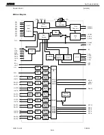
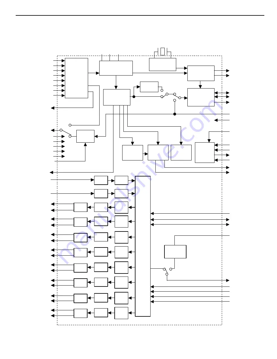
Block Diagram 


Input 

Selector 

Clock

Recovery

Clock 

Generator 

DAIF

Deco der

AC-3/MPEG

Detect

DEM

µ

P I/F 

Audio 

I/F 

X'tal

Oscillator

PDN 

INT0

LRCK2

BICK2

SDTO2

DAUX2

MCKO2

XTO

XTI

R

PVDD

PVSS 

CDTI

CDTO

CCLK

CSN

DVDD 

DVSS 

TVDD 

MCKO1

I2C

RX0 

RX1 

RX2 

RX3 

RX4 

RX5 

RX6 

RX7 

DIT 

TX0 

Error &

Detect

STATUS

INT1

Q-subcode

buffer

TX1 

B,C,U, 

VOUT 

8 to 3 

VIN 

Audio

I/F

SCF 

SCF 

SCF 

SCF 

SCF 

SCF 

LOUT1+ 

ROUT1+ 

LOUT2+ 

ROUT2+ 

LOUT3+ 

ROUT3+ 

DAC 

DATT

DEM

ADC 

HPF

ADC 

HPF

RIN 

LIN 

LRCK1

BICK1 

SDTI1 

SDTI2 

SDTI3 

DAUX1

MCLK

LRCK

BICK

SDOUT

SDIN1
SDIN2
SDIN3

MCLK

SDTO1

Format 

Converter

SDTI4 

SDIN4

SCF 

SCF 

LOUT4+ 

ROUT4+ 

DAC 

DATT

DEM

DAC 

DATT

DEM

DAC 

DATT

DEM

DAC 

DATT

DEM

DAC 

DATT

DEM

DAC 

DATT

DEM

DAC 

DATT

DEM

AVDD 

AVSS 

LOUT1- 

ROUT1- 

LOUT2- 

ROUT2- 

LOUT3- 

ROUT3- 

LOUT4- 

ROUT4- 


AVR340 


                harman/kardon 

100

Summary of Contents for AVR 340

Page 1: ...UNCTIONS 12 CONNECTIONS 16 OPERATION 19 TROUBLESHOOTING GUIDE 26 PROCESSOR RESET 26 BULLETIN HK2006 01 27 TECH TIP HK2003 01 28 DISASSEMBLY 29 UNIT EXPLODED VIEW 32 EXPLODED VIEW PARTS LIST 33 AMP BIA...

Page 2: ...or to applying power to the unit under test 2 After removing an electrical assembly equipped with ES devices place the assembly on a conductive surface such as aluminum foil to prevent electrostatic c...

Page 3: ...l overlays control shaft etc Plug the AC line cord of the appliance directly into a 120V AC 60Hz outlet and turn the AC power switch on Any current measured must not exceed o 5mA ANY MEASUREMENTS NOT...

Page 4: ...and S Video 10Hz 8MHz 3dB Video Frequency Response Component Video 10Hz 50MHz 3dB General Power Requirement AC 120V 60Hz Power Consumption 118W idle 890W maximum 7 channels driven Dimensions Product S...

Page 5: ...HMRSQTBSHNM L MT K EL 0 ONK MS TK BPW0 0 16Y BR 0 08Y 0 0 B QC V QQ MSX RGDDS FTHCD 1 A SSDQX RR X 3 8 2 L KNNO MSDMM RR X L MT K HMRSQTBSHNM 5 EL 0 ONKD MS TK 6 RS OKD 0 QDLNBNM RR X 1 5 QDLNBNM RR...

Page 6: ...it does Press the Tone Mode Button 5 until the desired option of TREBLE MODE or BASS MODE appears in the Lower Display Line and in the on screen display and then press either of the Buttons to enter...

Page 7: ...icators Tuner Mode Selector Press this button to select Auto or Manual tuning When the button is pressed so that the AUTO appears in the Lower Display Line the tuner will search for the next station w...

Page 8: ...will identify the station as AM or FM and show the frequency and preset number if any Lower Display Line Depending on the unit s sta tus a variety of messages will appear here In normal operation the...

Page 9: ...t in making the correct connections for multichannel input output and speaker connec tions all connection jacks and terminals are color coded in conformance with the CEA standards as follows Front Lef...

Page 10: ...th the CEA color code specification the green terminal is the positive or terminal that should be connected to the red terminal on speakers with the older color coding Connect the black terminal on th...

Page 11: ...sion capability if your video display device is equipped with component Y Pb Pr video inputs you need only to connect the Component Video Monitor Outputs fl to your display device and the AVR 340 will...

Page 12: ...c TV Video Selector d DMP Selector e 6 Channel 8 Channel Direct Input f Mute The BridgeTM s a b c d e f g h j n n p o o q r t v 32 30 29 28 36 37 38 39 z x 35 POWER MUTE AVR DVD AM FM CD TAPE VID2 VCR...

Page 13: ...VR 340 s output levels See pages 25 31 and 42 for more information on calibrating the AVR 340 j Sleep Button Press this button to place the unit in the Sleep mode After the time shown in the display t...

Page 14: ...Press this button to select a DTS Neo 6 mode These modes take a two channel stereo or matrix surround encoded source and create a full five six or seven channel sound field See pages 36 and 40 for th...

Page 15: ...Direct Input Press this button to select the device connected to the 6 8 Channel Direct Inputs X See page 34 for more information When the device connected to the 6 8 Channel Direct Input X is also a...

Page 16: ...loss of clarity or resolution we sug gest that you use high quality speaker cable Many brands of cable are available and the choice of cable may be influenced by the distance between your speakers and...

Page 17: ...elected you may view the component video output of the device connected to the Component Video 1 Inputs enabling you to view and listen to different sources Similarly it is recommended that you connec...

Page 18: ...e the amplifiers for surround operation by changing a setting in the MULTI ROOM SETUP menu following the instructions shown on page 46 NOTE The AVR 340 s multiroom system is only capa ble of distribut...

Page 19: ...switch to the digital input if selected component video input surround mode output levels and night mode status as well as any speaker configuration settings established by using the INDEPENDENT Bass...

Page 20: ...e front panel first press the Surround Mode Group Selector Button 7 until the desired major surround mode group such as Dolby DTS or Logic 7 is select ed Next press the Surround Mode Selector Button 8...

Page 21: ...eo audio output from a DVD to the DVD Audio Inputs Z on the rear panel when you connect the source s digital outputs If you have not already configured an input for a digital source using the on scree...

Page 22: ...ts fif or the front panel Digital Inputs To listen to a PCM digital source first select the input for the desired source e g CD Next press the Digital Select Button q and then use the Buttons n on the...

Page 23: ...playing you may not be able to select some of the analog surround modes such as Dolby Pro Logic II or IIx Dolby 3 Stereo Hall Theater or Logic 7 Refer to the tables on page 40 for more information Wh...

Page 24: ...ting Slow scale and adjust the volume until the meter reads 75dB Once the reference level has been set press the Channel Select Button m and FRONT L LEVEL will appear in the Lower Display Line Q and s...

Page 25: ...s without turning the unit off press the Dim Button h as needed until the displays are on In addition to lowering the brightness of the displays or turning them off completely you may wish to have the...

Page 26: ...DVD display and digital audio stops Check that Digital Input is selected In addition to the items shown above additional information on troubleshooting possible problems with your AVR 340 or installat...

Page 27: ...ACTION AVR135 AN0020 28676 to AN0020 33475 May Need Modification Replace Wafer AVR140 AN0031 04201 to AN0031 16800 May Need Modification Replace Wafer AVR240 AN0032 01001 to AN0032 13000 May Need Modi...

Page 28: ...R300 C906 Front PCB 0 1Farad 5 5v capacitor J4433210421X or P10791 ND AVR500 C906 Front PCB 0 1Farad 5 5v capacitor J4433210421X or P10791 ND AVR110 210 310 510 AVR120 220 320 520 C216 Front PCB 0 047...

Page 29: ...f sgd Eqnms O mdk 0 8 5 2 7 3 6 Qdlnud sgd Rbqdvr 3 Qdlnuhmf sgd L hm OBA 0 1 4 0 7 12 30 0 32 Qdlnud sgd Rbqdvr 20 08 07 06 05 22 21 04 03 02 00 0 8 7 24 23 25 26 27 28 3 4 6 5 3 2 1 0 10 11 2 Qdlnuh...

Page 30: ...2 3 Pull out the Volume Knob ASS Y 3 Rotary Knobs 5 4 Remove 10 screws S2 S14 and then remove the Tone PCB 37 3 5 Disconnect the lead wire BN84 5P One the Tone PCB 37 3 from connector CN84 on the Fip...

Page 31: ...ard canle on the Fip PCB 37 1 from connector CN72 on the Input PCB 39 1 5 Remove 11 screws S8 S11 and then remove the Input PCB 39 1 11 Download PCB 37 9 REMOVAL 1 Remove the Top cabinet referring to...

Page 32: ...8 3LAYF16 BAS0 8 4LAXF16 BLC1 332 BAS0 708J017 JFA0 047Y BLY0 77 BFK0 110 BFW0 227LAF16 O QSR MN BLG0 103 R3 R3 R0 28 0 R3 3 0 2 18 R01 25 R8 R4 R3 R00 R5 27 0 21 22 41 R02 R7 24 23 0 0 0 0 0 1 0 1 0...

Page 33: ...AVR340 harman kardon 33...

Page 34: ...VOLTMETER Connect to CN81 CN82 CN83 CN84 CN85 CN86 CN87 NO Channel Adjust for Adjustment 1 Front Left 25 92mV 5 VR83 CN82 VR86 2 Front Right 25 92mV 5 25 92mV 5 25 92mV 5 25 92mV 5 VR84 CN86 VR82 3 C...

Page 35: ...AVR340 harman kardon 35...

Page 36: ...T CAP CERAMIC 0 022UF 50V Z 1 EA C799 CCEA1CH101T CAP ELECT 100UF 16V 1 EA C859 HCBS1H223ZFT CAP CERAMIC 0 022UF 50V Z 1 EA C860 HCBS1H223ZFT CAP CERAMIC 0 022UF 50V Z 1 EA C861 HCBS1H223ZFT CAP CERAM...

Page 37: ...470T RES CARBON 47 OHM 1 5W J 1 EA R710 CRD20TJ470T RES CARBON 47 OHM 1 5W J 1 EA R711 CRD20TJ470T RES CARBON 47 OHM 1 5W J 1 EA R712 CRD20TJ102T RES CARBON 1K OHM 1 5W J 1 EA R713 CRD20TJ102T RES CAR...

Page 38: ...S CARBON 10K OHM 1 5W J 1 EA R888 CRD20TJ103T RES CARBON 10K OHM 1 5W J 1 EA R889 CRD20TJ103T RES CARBON 10K OHM 1 5W J 1 EA R890 CRD20TJ103T RES CARBON 10K OHM 1 5W J 1 EA R891 CRD20TJ103T RES CARBON...

Page 39: ...DIODE 1SS133 1 EA D787 HVD1SS133MT DIODE 1SS133 1 EA PCB FRONT PANEL KEY CUP11818 2 Capacitors C720 HCBS1H181KBT CAP CERAMIC 180PF 50V K 1 EA C721 HCBS1H181KBT CAP CERAMIC 180PF 50V K 1 EA C730 CCFT1...

Page 40: ...CEA1VH100T CAP ELECT 10UF 35V 1 EA C843 CCEA1VH100T CAP ELECT 10UF 35V 1 EA C855 HCBS1H101KBT CAP CERAMIC 100PF 50V K 1 EA C856 HCBS1H101KBT CAP CERAMIC 100PF 50V K 1 EA C857 HCBS1H104ZFT CAP CERAMIC...

Page 41: ...HCBS1H223ZFT CAP CERAMIC 0 022UF 50V Z 1 EA D788 HVDMTZJ5 6BT DIODE ZENER 5 6V 1 EA D789 HVDMTZJ5 6BT DIODE ZENER 5 6V 1 EA R808 CRD20TJ102T RES CARBON 1K OHM 1 5W J 1 EA R809 CRD20TJ102T RES CARBON...

Page 42: ...CAP CHIP 0 1UF 1 EA C309 HCUS1H332KC CAP CHIP 3300PF 1 EA C310 HCUS1H332KC CAP CHIP 3300PF 1 EA C311 HCUS1H332KC CAP CHIP 3300PF 1 EA C312 HCUS1H332KC CAP CHIP 3300PF 1 EA C313 HCUS1H332KC CAP CHIP 3...

Page 43: ...A C415 HCUS1H223KC CAP CHIP 2200PF 1 EA C416 HCUS1H223KC CAP CHIP 2200PF 1 EA C417 HCUS1H223KC CAP CHIP 2200PF 1 EA C418 HCUS1H223KC CAP CHIP 2200PF 1 EA C419 HCUS1H223KC CAP CHIP 2200PF 1 EA C420 HCU...

Page 44: ...CUS1H104ZF CAP CHIP 0 1UF 1 EA C591 HCUS1H151JA CAP CHIP 150PFJA 150PF 1 EA C599 HCUS1H390JA CAP CHIP 39PF 1 EA C600 HCUS1H390JA CAP CHIP 39PF 1 EA C701 HCUS1H330JA CAP CHIP 33PF 1 EA C702 HCUS1H330JA...

Page 45: ...0T CAP ELECT 10UF 35V 1 EA C269 CCEA1VH100T CAP ELECT 10UF 35V 1 EA C341 CCEA1VH100T CAP ELECT 10UF 35V 1 EA C342 CCEA1VH100T CAP ELECT 10UF 35V 1 EA C343 CCEA1VH100T CAP ELECT 10UF 35V 1 EA C344 CCEA...

Page 46: ...70UF 10V 1 EA C724 CCEA1AH471T CAP ELECT 470UF 10V 1 EA C726 CCEA1CH101T CAP ELECT 100UF 16V 1 EA C728 CCEA1AH471T CAP ELECT 470UF 10V 1 EA C730 CCEA1CH101T CAP ELECT 100UF 16V 1 EA C732 CCEA1CH101T C...

Page 47: ...HVTKTA2014GR TRANSISTOR SMD KTA2014GR 1 EA D201 HVD1SS133MT DIODE 1SS133T 1 EA D202 HVD1SS133MT DIODE 1SS133T 1 EA D203 HVD1SS133MT DIODE 1SS133T 1 EA D204 HVD1SS133MT DIODE 1SS133T 1 EA D205 HVD1SS1...

Page 48: ...CRJ10DJ471T RES CHIP 470 OHM 1 EA R208 CRJ10DJ471T RES CHIP 470 OHM 1 EA R209 CRJ10DJ471T RES CHIP 470 OHM 1 EA R210 CRJ10DJ471T RES CHIP 470 OHM 1 EA R211 CRJ10DJ471T RES CHIP 470 OHM 1 EA R212 CRJ1...

Page 49: ...HIP 470 OHM 1 EA R275 CRJ10DJ472T RES CHIP 4 7K OHM 1 EA R276 CRJ10DJ472T RES CHIP 4 7K OHM 1 EA R277 CRJ10DJ472T RES CHIP 4 7K OHM 1 EA R278 CRJ10DJ104T RES CHIP 100K OHM 1 EA R279 CRJ10DJ104T RES CH...

Page 50: ...ES CHIP 1 2K OHM 1 EA R352 CRJ10DJ122T RES CHIP 1 2K OHM 1 EA R353 CRJ10DJ122T RES CHIP 1 2K OHM 1 EA R356 CRJ10DJ122T RES CHIP 1 2K OHM 1 EA R361 CRJ10DJ104T RES CHIP 100K OHM 1 EA R362 CRJ10DJ104T R...

Page 51: ...102T RES CHIP 1K OHM 1 EA R433 CRJ10DJ101T RES CHIP 100 OHM 1 EA R434 CRJ10DJ101T RES CHIP 100 OHM 1 EA R435 CRJ10DJ101T RES CHIP 100 OHM 1 EA R436 CRJ10DJ101T RES CHIP 100 OHM 1 EA R437 CRJ10DJ101T R...

Page 52: ...RES CHIP 75 OHM 1 EA R586 CRJ10DJ820T RES CHIP 82 OHM 1 EA R587 CRJ10DJ910T RES CHIP 91 OHM 1 EA R588 CRJ10DJ750T RES CHIP 75 OHM 1 EA R590 CRJ10DJ222T RES CHIP 2 2K OHM 1 EA R591 CRJ10DJ222T RES CHIP...

Page 53: ...G2ANJ330H RES METAL OXIDE FILM 33 OHM 2W J 1 EA Miscellaneous L701 HLZ9Z014Z CHIP BEAD HU 1H4516 600JT 1 EA L702 HLZ9Z014Z CHIP BEAD HU 1H4516 600JT 1 EA L703 HLZ9Z014Z CHIP BEAD HU 1H4516 600JT 1 EA...

Page 54: ...330PF 1 EA C450 CCEA1VH331T CAP ELECT 330UF 35V 1 EA C451 CCEA1VH100T CAP ELECT 10UF 35V 1 EA C452 CCEA1VH100T CAP ELECT 10UF 35V 1 EA C467 HCUS1C105ZF CAP CHIP 1UF 1 EA C468 HCUS1C105ZF CAP CHIP 1UF...

Page 55: ...EA R489 CRJ10DJ392T RES CHIP 3 9K OHM 1 EA R490 CRJ10DJ392T RES CHIP 3 9K OHM 1 EA R499 CRJ10DJ102T RES CHIP 1K OHM 1 EA Miscellaneous CN12 CJP03GA19ZY WAFER STRAIGHT 3PIN WAFER 1 EA JK16 CJJ4N076Z JA...

Page 56: ...Z 1 EA C451 CCEA1CH101T CAP ELECT 100UF 16V 1 EA C452 HCBS1H223ZFT CAP CERAMIC 0 022UF 50V Z 1 EA C453 CCEA1CH101T CAP ELECT 100UF 16V 1 EA C454 HCBS1H223ZFT CAP CERAMIC 0 022UF 50V Z 1 EA C455 CCEA1...

Page 57: ...1 EA IC42 HVINJM2296M I C VIDEO SW NJM2296M JRC 1 EA IC43 HVINJM2296M I C VIDEO SW NJM2296M JRC 1 EA IC44 HVIHCF4053M013T I C HCF4053 TRIPLE 2 CHAN MULTPLX ST 1 EA IC45 HVIHCF4053M013T I C HCF4053 TR...

Page 58: ...6 CRD20TJ102T RES CARBON 1K OHM 1 5W J 1 EA R447 CRD20TJ750T RES CARBON 75 OHM 1 5W J 1 EA R448 CRD20TJ1R8T RES CARBON 1 8 OHM 1 5W J 1 EA R449 CRD20TJ102T RES CARBON 1K OHM 1 5W J 1 EA R450 CRD20TJ10...

Page 59: ...3T RES CARBON 22K OHM 1 5W J 1 EA Miscellaneous BN14 CWB4F232450PU WIRE ASS Y WIRE 1 EA BN91 CWB4FE53130PU WIRE ASS Y WIRE 1 EA CN14 CJP06GA19ZY WAFER STRAIGHT 6PIN WAFER 1 EA CN41 CJP06GA19ZY WAFER S...

Page 60: ...ON 75 OHM 1 5W J 1 EA R602 CRD20TJ750T RES CARBON 75 OHM 1 5W J 1 EA R603 CRD20TJ750T RES CARBON 75 OHM 1 5W J 1 EA R604 CRD20TJ750T RES CARBON 75 OHM 1 5W J 1 EA R605 CRD20TJ750T RES CARBON 75 OHM 1...

Page 61: ...1 OHM 1 5W J 1 EA R763 CRD20TJ1R0T RES CARBON 1 OHM 1 5W J 1 EA R764 CRD20TJ102T RES CARBON 1K OHM 1 5W J 1 EA R765 CRD20TJ104T RES CARBON 100K OHM 1 5W J 1 EA R766 CRD20TJ472T RES CARBON 4 7K OHM 1...

Page 62: ...CHOTTKY 1N5819 1 EA D108 KVD1N4003ST DIODE 1N4003 1 EA D109 HVDMTZJ12BT DIODE ZENER 12V 1 2W 1 EA D111 HVDMTZJ12BT DIODE ZENER 12V 1 2W 1 EA D950 KVD1N4003ST DIODE 1N4003 1 EA D951 KVD1N4003ST DIODE 1...

Page 63: ...35V 1 EA C930 CCEA1VH222F CAP ELEC ANGLE 2200UF 35V 1 EA C935 CCKT1H223ZF CAP CERAMIC 0 022UF 50V ZF 1 EA C936 CCKT1H223ZF CAP CERAMIC 0 022UF 50V ZF 1 EA C937 CCKT1H223ZF CAP CERAMIC 0 022UF 50V ZF...

Page 64: ...RH0615C100221 1 EA VR87 HVN1RA221B01T RES SEMI FIXED 220 OHM RH0615C100221 1 EA VR88 HVN1RA221B01T RES SEMI FIXED 220 OHM RH0615C100221 1 EA Miscellaneous CN31 CJP02GB46ZY WAFER ANGLE 2PIN WAFER 1 EA...

Page 65: ...D20TJ102T RES CARBON 1K OHM 1 5W J 1 EA R904 CRD20TJ102T RES CARBON 1K OHM 1 5W J 1 EA R905 CRD20TJ104T RES CARBON 100K OHM 1 5W J 1 EA R906 CRD20TJ104T RES CARBON 100K OHM 1 5W J 1 EA R907 CRD20TJ562...

Page 66: ...OUT PCB CUP11849 12 C953 HCBS1H104ZFT CAP CERAMIC 0 1UF 50V Z 1 EA CN87 CJP02GA19ZY WAFER 2PIN WAFER 1 EA CN88 CJP04GA19ZY WAFER STRAIGHT 4PIN WAFER 1 EA D952 HVD1SS133MT DIODE 1SS133T 1 EA D953 HVD1...

Page 67: ...J10DJ470T RES CHIP 47 OHM 1 EA R406 CRJ10DJ474T RES CHIP 470K OHM 1 EA R407 CRJ10DJ474T RES CHIP 470K OHM 1 EA R412 CRJ10DJ471T RES CHIP 470 OHM 1 EA R413 CRJ10DJ471T RES CHIP 470 OHM 1 EA R419 CRJ10D...

Page 68: ...B CAP CERAMIC 220PF 50V KB 1 EA C722 CCKT1H221KB CAP CERAMIC 220PF 50V KB 1 EA C723 CCKT1H221KB CAP CERAMIC 220PF 50V KB 1 EA C724 CCKT1H221KB CAP CERAMIC 220PF 50V KB 1 EA C725 CCKT1H221KB CAP CERAMI...

Page 69: ...YLAR 0 047UF 50V J 1 EA C997 HCQI1H473JZT CAP MYLAR 0 047UF 50V J 1 EA C999 CCKT1H223ZF CAP CERAMIC 0 022UF 50V ZF 1 EA C563 CCEA1CH101T CAP ELECT 100UF 16V 1 EA C565 CCEA1CH101T CAP ELECT 100UF 16V 1...

Page 70: ...R KTA1268GR 1 EA Q503 HVTKTA1268GRT TRANSISTOR KTA1268GR 1 EA Q504 HVTKTA1268GRT TRANSISTOR KTA1268GR 1 EA Q505 HVTKTA1268GRT TRANSISTOR KTA1268GR 1 EA Q511 HVTKTC3200GRT TRANSISTOR KTC3200GR 1 EA Q51...

Page 71: ...C3200GRT TRANSISTOR KTC3200GR 1 EA Q822 HVTKTC3200GRT TRANSISTOR KTC3200GR 1 EA Q823 HVTKTC3200GRT TRANSISTOR KTC3200GR 1 EA Q824 HVTKTC3198YT TRANSISTOR KTC3198Y 1 EA Q825 HVTKTC3198YT TRANSISTOR KTC...

Page 72: ...T2SC3423O TRANSISTOR 2SC3423O 1 EA Q886 HVT2SC3423O TRANSISTOR 2SC3423O 1 EA Q887 HVT2SC3423O TRANSISTOR 2SC3423O 1 EA IC94 HVIMC7805C I C REGULATOR MC7805 KA7805 ABTU 1 EA Resistors R501 CRD20TJ433T...

Page 73: ...EA R573 CRD20TJ561T RES CARBON 560 OHM 1 5W J 1 EA R574 CRD20TJ561T RES CARBON 560 OHM 1 5W J 1 EA R575 CRD20TJ561T RES CARBON 560 OHM 1 5W J 1 EA R576 CRD20TJ100T RES CARBON 10 OHM 1 5W J 1 EA R577 C...

Page 74: ...CARBON 47 OHM 1 4W 1 EA R668 CRD25TJ470T RES CARBON 47 OHM 1 4W 1 EA R669 CRD25TJ470T RES CARBON 47 OHM 1 4W 1 EA R670 CRD25TJ470T RES CARBON 47 OHM 1 4W 1 EA R671 CRD20TJ911T RES CARBON 910 OHM 1 5W...

Page 75: ...75 OHM 1 5W J 1 EA R782 CRD20TJ750T RES CARBON 75 OHM 1 5W J 1 EA R783 CRD20TJ750T RES CARBON 75 OHM 1 5W J 1 EA R784 CRD20TJ750T RES CARBON 75 OHM 1 5W J 1 EA R785 CRD20TJ750T RES CARBON 75 OHM 1 5W...

Page 76: ...EA R867 CRD20TJ472T RES CARBON 4 7K OHM 1 5W J 1 EA R868 CRD20TJ473T RES CARBON 47K OHM 1 5W J 1 EA R869 CRD20TJ473T RES CARBON 47K OHM 1 5W J 1 EA R870 CRD20TJ433T RES CARBON 43K OHM 1 5W J 1 EA R87...

Page 77: ...A R973 CRD20TJ472T RES CARBON 4 7K OHM 1 5W J 1 EA R974 CRD20TJ331T RES CARBON 330 OHM 1 5W J 1 EA R975 CRD20TJ331T RES CARBON 330 OHM 1 5W J 1 EA R976 CRD20TJ331T RES CARBON 330 OHM 1 5W J 1 EA R977...

Page 78: ...050EN WIRE ASS Y WIRE 1 EA BN88 CWB2B904070EN WIRE ASS Y WIRE 1 EA BN97 CWZAVR340BN97 WIRE ASS Y WIRE 1 EA BN98 HJP08GA130ZK WAFER WAFER 1 EA CN61 KJP02GA01ZM WAFER WAFER 1 EA CN62 KJP02GA01ZM WAFER W...

Page 79: ...1 EA L506 CLEY0R5KAK COIL SPEAKER 0 5UH K 1 EA L507 CLEY0R5KAK COIL SPEAKER 0 5UH K 1 EA RY94 HSL1A008ZE RELAY SDT S 112DMR 1 EA TH91 KRTP42T7D330B THERMAL SENSOR POSISTOR POSISTOR 1 EA T902 CLT5J038...

Page 80: ...AVR340 harman kardon...

Page 81: ...AVR340 harman kardon...

Page 82: ...AVR340 harman kardon 82...

Page 83: ...CAM350 PRO V 7 6 Mon Sep 01 10 29 56 2003 Untitled AVR340 harman kardon 83...

Page 84: ...AVR340 harman kardon 84...

Page 85: ...AVR340 harman kardon 85...

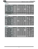
Page 86: ...Order Number Package Number Package Description 74AC04SC M14A 14 Lead Small Outline Integrated Circuit SOIC JEDEC MS 120 0 150 Narrow Body 74AC04SJ M14D 14 Lead Small Outline Package SOP EIAJ TYPE II...

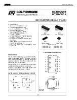
Page 87: ...10 LSTTL LOADS SYMMETRICAL OUTPUT IMPEDANCE IOH IOL 4 mA MIN BALANCED PROPAGATION DELAYS tPLH tPHL WIDE OPERATING VOLTAGE RANGE VCC OPR 2 V TO 6 V PIN AND FUNCTION COMPATIBLE WITH 54 74LS04 The M54 74...

Page 88: ...CU04AFN IC72 76 LOGIC SYMBOL TRUTH TABLE 1 2 3 4 5 6 7 1A 1Y 2A 2Y 3A 3Y GND 6A 6Y 5A 5Y 4A 4Y Vcc 14 13 12 11 10 9 8 A L H Y H L 1A 1 3 5 9 11 13 2A 3A 4A 5A 6A 1Y 2Y 3Y 4Y 5Y 6Y 2 4 6 8 10 12 AVR340...

Page 89: ...iver 10MHz with 75 driver 7MHz 4 Cross talk 70dB When 4 43MHz 5 With SAG measures pin 75 driver and Y C mix driver Applications 1 TV 2 VTR 3 Video camera 4 Digital still camera 5 Other visual equipmen...

Page 90: ...MITSUMI Video Switch 75 driver Y C mix MM1501 MM1507 MM1508 MM1509 MM1510 MM1511 MM1512 AVR340 harman kardon 90...

Page 91: ...PSH Refer to measurement procedures 1 8 V Input pin voltage VIN No signal no load 1 75 1 95 2 15 V Output pin voltage VOUT No signal no load 2 35 V Voltage gain GV Refer to measurement procedures 5 5...

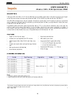
Page 92: ...t count sequence sequential or interleave A burst of read or write cycles in progress can be terminated by a burst terminate command or can be interrupted and replaced by a new burst read or write com...

Page 93: ...26 DQ7 LDQM PIN DESCRIPTION PIN PIN NAME DESCRIPTION CLK Clock The system clock input All other inputs are referenced to the SDRAM on the rising edge of CLK CKE Clock Enable Controls internal clock si...

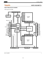
Page 94: ...DQ15 Address Register I O Control Test Mode Mode Register Self Refresh Counter Column Decoder Sense AMP I O gates 512Kx16 Bank 0 Column Decoder Sense AMP I O gates 512Kx16 Bank 1 RAS CAS CS WE UDQM LD...

Page 95: ...Active H X L L H H X Row Address V Read H X L H L H X Column Address L V Read with Auto precharge H Write H X L H L L X Column Address L V Write with Auto precharge H Precharge All Bank H X L L H L X...

Page 96: ...ess Pb Free DQFN package Ordering Code Devices also available in Tape and Reel Specify by appending the suffix letter X to the ordering code Pb Free package per JEDEC J STD 020B Note 1 DQFN package av...

Page 97: ...X32 Logic Symbol IEEC IEC Pin Descriptions Connection Diagrams Pin Assignments for SOIC SOP and TSSOP Pad Assignment for DQFN Top View Pin Names Description An Bn Inputs On Outputs AVR340 harman kardo...

Page 98: ...8 channel input selector and can automatically detect a Non PCM bit stream The AK4589 provides a compatibility of hardware and software with the AK4588 Dolby Digital AC 3 is a trademark of Dolby Labor...

Page 99: ...Detection 32kHz 44 1kHz 48kHz 88 2kHz 96kHz 176 4kHz 192kHz Unlock Parity Error Detection Validity Flag Detection Up to 24bit Audio Data Format Audio I F Master or Slave Mode 40 bit Channel Status Bu...

Page 100: ...RX7 DIT TX0 Error Detect STATUS INT1 Q subcode buffer TX1 B C U VOUT 8 to 3 VIN Audio I F SCF SCF SCF SCF SCF SCF LOUT1 ROUT1 LOUT2 ROUT2 LOUT3 ROUT3 DAC DATT DEM ADC HPF ADC HPF RIN LIN LRCK1 BICK1...

Page 101: ...5 36 37 38 39 40 60 59 58 57 56 55 54 53 52 51 50 49 48 47 46 45 44 43 42 41 80 79 78 77 76 75 74 73 72 71 70 69 68 67 66 65 64 63 62 61 1 2 3 4 5 6 7 8 9 10 11 12 13 14 15 16 17 18 19 20 INT1 BOUT TV...

Page 102: ...a Clock Pin DIR DIT part 16 LRCK2 I O Channel Clock Pin DIR DIT part 17 SDTO1 O Audio Serial Data Output Pin ADC DAC part 18 BICK1 I O Audio Serial Data Clock Pin ADC DAC part 19 LRCK1 I O Input Chann...

Page 103: ...Negative Analog Output Pin 38 ROUT4 O DAC4 Rch Positive Analog Output Pin 470pF capacitor should be connected between ROUT4 and ROUT4 39 LOUT3 O DAC3 Lch Negative Analog Output Pin 40 LOUT3 O DAC3 Lch...

Page 104: ...d pin Internally biased at PVDD 2 64 PVSS PLL Ground pin 65 R External Resistor Pin 12k 1 resistor should be connected to PVSS externally 66 PVDD PLL Power supply Pin 4 75V 5 25V 67 RX4 I Receiver Cha...

Page 105: ...TM programming structure and Framework module library Dolby Digital Pro Logic II DTS Digital Surround MPEG Multichannel and Cirrus Original Surround 6 1 PCM Effects Processor capable of generating suc...

Page 106: ...ion notes AN208 and their corresponding appendices are available through the Crystal WareTM Software Licensing Program Please refer to AN208 for the latest listing of application codes for DSPAB DSPC...

Page 107: ...with a generous amount of on chip program and data RAM and has all necessary peripherals required to support the latest standards in consumer entertainment products such as AV receivers and DVD Audio...

Page 108: ...0 and lists all of its names Please refer to this section when exact pin numbers are in question 3 2 Termination Requirements The CS49400 incorporates open drain pins which must be pulled high for pro...

Page 109: ...lly possible to each power pin The 0 1uF capacitor should be closest to the part typically 5mm or closer 4 2 Analog Power Conditioning In order to obtain the best performance from the CS49400 s intern...

Page 110: ...7 SD_ADDR6 EXTA6 SD_ADDR5 EXTA5 SD_ADDR4 EXTA4 SD_ADDR3 EXTA3 SD_ADDR2 EXTA2 SD_ADDR1 EXTA1 SD_ADDR0 EXTA0 SD_CLK_OUT SD_CLK_IN SD_DATA8 EXTA11 SD_DATA7 EXTD7 SD_DATA6 EXTD6 SD_DATA5 EXTD5 SD_DATA4 EX...

Page 111: ...6 EXTD4 EXTA18 VSSSD4 EXTD5 EXTD3 EXTA17 EXTA16 EXTA15 EXTA14 EXTA13 EXTA12 EXTA11 EXTA8 EXTA7 EXTA6 EXTA5 EXTA4 VDDSD1 EXTA10 EXTA0 EXTA1 EXTA2 EXTA3 SDATAN2 GPIO26 SDATAN1 GPIO25 SDATAN0 GPIO24 LRCL...

Page 112: ...PUT XTALO Crystal Oscillator Output Crystal oscillator output OUTPUT CLKSEL DSP Clock Select This pin selects the internal source clock When CLKSEL is low CLKIN is connected to the internal PLL from w...

Page 113: ...host mode this pin can serve as the external memory active low write enable output signal BIDIRECTIONAL Default INPUT FCS Host Parallel Chip Select Host Serial SPI Chip Select In parallel host mode th...

Page 114: ...2 channels of PCM data FSDATAN2 can be sampled with either edge of FSCLKN2 depending on how FSCLKN2 has been configured BIDIRECTIONAL Default INPUT FDBCK Reserved This pin is reserved and should be pu...

Page 115: ...s an input SCLK1 is independent of MCLK BIDIRECTIONAL Default INPUT LRCLK0 Audio Output Sample Rate Clock Bidirectional digital audio output frame clock for AUDATA0 AUDATA1 AUDATA2 and AUDATA3 As an o...

Page 116: ...n also act as a general purpose input or output that can be individually configured and controlled by DSPC BIDIRECTIONAL Default OUTPUT DBCK Debug Clock Must be tied high to 3 3k ohm resistor INPUT DB...

Page 117: ...at can be individually configured and controlled by DSPC BIDIRECTIONAL Default INPUT SCS Host Serial SPI Chip Select SPI mode active low chip select input signal INPUT SCCLK Serial Control Port Clock...

Page 118: ...1 Host Parallel Output Enable Host Parallel R W General Purpose I O In Intel parallel host mode this pin serves as the active low data bus enable input In Motorola parallel host mode this pin serves a...

Page 119: ...ATA11 EXTA14 SD_DATA10 EXTA13 SD_DATA9 EXTA12 SD_DATA8 EXTA11 SDRAM data bus 15 8 SRAM external address bus 18 11 OUTPUT SD_DATA7 EXTD7 SDRAM Data Bus SRAM External Data Bus SD_DATA6 EXTD6 SD_DATA5 EX...

Page 120: ...trobe SDRAM column address strobe OUTPUT SD_WE SDRAM Write Enable SDRAM write enable OUTPUT SD_DQM1 SDRAM Data Mask 1 SDRAM data mask 1 OUTPUT SD_DQM0 SDRAM Data Mask 2 SDRAM data mask 0 OUTPUT NV_CS...

Page 121: ...is one of three pins used to select the control port mode This pin can act as a general purpose input or output that can be individually configured and controlled by DSPC BIDIRECTIONAL Default INPUT...

Page 122: ...5 1 No Connect Recommended tie to ground VDDSD 4 1 3 3V SDRAM SRAM EPROM Interface Supply 3 3V SDRAM SRAM EPROM supply VSSSD 3 3V SDRAM SRAM EPROM Interface Ground 3 3V ground AVR340 harman kardon 12...

Page 123: ...AVR340 harman kardon 123...

Page 124: ...AVR340 harman kardon 124...

Page 125: ...AVR340 harman kardon 125...

Page 126: ...AVR340 harman kardon 126...

Page 127: ...ES CMOS DEVICES DESCRIPTION The HCF4053B is a monolithic integrated circuit fabricated in Metal Oxide Semiconductor technology available in DIP and SOP packages The HCF4053B analog multiplexer demulti...

Page 128: ...0 9 A B C Binary Control Inputs 6 INH Inhibit Inputs 12 13 2 1 5 3 IN OUT ax ay bx by cx cy Input Output 14 OUT IN ax or ay 15 OUT IN bx or by 4 OUT IN cx or cy 7 VEE Supply Voltage 8 VSS Negative Sup...

Page 129: ...AVR340 harman kardon 129...

Page 130: ...AVR340 harman kardon 130...

Page 131: ...AVR340 harman kardon 131...

Page 132: ...AVR340 harman kardon 132...

Page 133: ...AVR340 harman kardon 133...

Page 134: ...AVR340 harman kardon 134...

Page 135: ...AVR340 harman kardon 135...

Page 136: ...AVR340 harman kardon 136...

Page 137: ...AVR340 harman kardon 137...

Page 138: ...PAL format FEATURES TV format NTSC 3 58 PAL M PAL and N PAL Dynamic comb filter Vertical edge enhancement circuit PLL 8 multiplier circuit Internal 8 bit 4 fsc AD converter Internal 8 bit precision 8...

Page 139: ...TC90A49P F BLOCK DIAGRAM PIN ASSIGNMENT AVR340 harman kardon 139...

Page 140: ...VRT ADC input range D upper limit voltage Stabilize by attaching a 0 01 F capacitor 4 5 AIN ADC input Inputs 1 0 Vp p video signal Sync tip clamp is performed I 5 6 VRB ADC input range D lower limit...

Page 141: ...0 is 1 used as vertical edge enhancement circuit ON OFF switch I 13 15 CKIN Clock input pin Pin 13 put a sine wave which is locked to the frequency of the burst signal in the input video signal Ampli...

Page 142: ...ge D upper limit voltage Stabilize by attaching a 0 01 F capacitor 19 23 DAVRB DAC output range D lower limit voltage Stabilize by attaching a 0 01 F capacitor 20 24 YOUT Outputs luminance signal Exte...

Page 143: ...2 Driver 6ch Y C MIX and PY Pb Pr for progressive 3 Group delay difference between chroma signal and luminance signal is a small number of nsec 4 Drive 2 lines of each signal 5 Operating by 5V single...

Page 144: ...9 18 17 23 1 5 6M BPF COUT CTRAP MUTE1 CIN GND GND YIN PYIN VCC GND VCC PbIN PYTRAP PrIN MUTE2 GND PrTRAP TEST MIXOUT MIXFB GND GND GND GND YTRAP YOUT PYOUT YFB PYFB PbOUT PrOUT N C MUTE1 TEST 20k 20k...

Page 145: ...ma signal and color difference signal Bias type input The input impedance is 20k Signal input terminal Input terminal for luminance signal Di clamp input 24 25 29 30 MIXFB MIXOUT YFB YOUT Signal outpu...

Page 146: ...progressive type 1 27 10 16 CTPAP YTRAP PYTRAP PrTRAP Terminal for LC resonance 6 11 VCC Power supply voltage VCC is separated into 6 pin and 11 pin That is to say C MIX and Y are partitioned by 6 pin...

Page 147: ...n description Input output equivalent circuit 12 MUTE2 Mute control terminal PY Pb and PR are muted simultaneously by setting MUTE to L 31 TEST Test terminal Usually short circuit this terminal to GND...

Page 148: ...AVR340 harman kardon 148...

Page 149: ...25 command switch During output functions as general output port or character data output command switch Low 525 lines high 625 lines NTSC PAL switch input output Switches the color mode between NTSC...

Page 150: ...LC74763 74763M Pin Assignment Serial Data Input Timing No 5039 4 19 Top view AVR340 harman kardon 150...

Page 151: ...LC74763M BLOCK DIAGRAM AVR340 harman kardon 151...

Page 152: ...T2 PA1 OUT1 PA0 OUT0 P97 IN1 P96 IN0 P95 PPG5 P94 PPG4 P93 FRCK ADTG CS3 P92 SCK1 CS2 P91 SOT1 CS1 P90 SIN1 CS0 P87 IRQ7 P86 IRQ6 P85 IRQ5 P84 IRQ4 P83 IRQ3 P82 IRQ2 MD2 80 79 78 77 76 75 74 73 72 71...

Page 153: ...pins function as the external data bus high output pins 99 100 1 2 1 to 4 P20 to P23 E CMOS H This is a general purpose I O port When the bits of external address output control register HACR are set...

Page 154: ...his is a general purpose I O port A04 In non multiplex mode this pin functions as an external address pin BIN1 8 16 bit up down counter input pin channel 1 13 15 P35 E CMOS H This is a general purpose...

Page 155: ...ternal bus mode this pin functions as the lower data write strobe output WRL pin When the WRE bit in the EPCR regis ter is set to 0 this pin functions as a general purpose I O port 71 73 P53 D CMOS Th...

Page 156: ...ese are the analog input pins 41 to 44 43 to 46 P64 to P67 H CMOS These are general purpose I O ports AN4 to AN7 These are the analog input pins 25 27 P70 G CMOS H This is a general purpose I O port S...

Page 157: ...hen the A D converter is in use this pin functions as the external trigger input pin CS3 Chip select 3 60 62 P94 D CMOS This is a general purpose I O port PPG4 PPG timer output pin 61 63 P95 D CMOS Th...

Page 158: ...AVR340 harman kardon 158...

Page 159: ...AVR340 harman kardon 159...

Page 160: ...nd other high quality AV systems FEATURES Operating Voltage 4 5 to 5 5V Wide frequency range 50MHz at 0dB typ Internal 6dB Amplifier Internal 75 Driver Circuit 2 system drive Power Save Circuit Bipola...

Page 161: ...DE EQUIVALENT CIRCUIT 1 3 5 VIN1 VIN2 VIN3 Input VIN1 VIN2 VIN3 V 100 20K 13 11 9 VOUT1 VOUT2 VOUT3 Output VOUT1 VOUT2 VOUT3 V 5 5K V 7 PowerSave Power Save 50K 30K PowerSave 14 12 10 V 1 V 2 V 3 V 2...

Page 162: ...AVR340 harman kardon 162...

Page 163: ...TO 92 SOT 89 SOT 23 5 Pin No Symbol 1 OUT 2 VDD 3 GND 4 NC 5 NC Pin No Symbol 1 OUT 2 VDD 3 GND Pin No Symbol 1 OUT 2 VDD 3 GND 1 2 3 mark side 1 2 3 mark side 1 2 3 mark side 5 4 IC87 RE5VL28CATZ IC...

Page 164: ...R S R S R COM R S R S R COM R S R COM DATA CK LEVEL SHIFTER 2 1 2 1 3 4 2 5 6 3 7 4 1 2 1 3 4 2 5 6 3 7 4 1 3 4 5 6 7 8 9 10 14 28 11 12 13 27 26 25 24 23 22 21 20 19 18 17 16 15 LATCH CIRCUIT SHIFT...

Page 165: ...S R COM R S R S R COM R S R S R COM DATA CK LEVEL SHIFTER 2 1 2 3 1 4 5 6 2 7 8 3 1 2 3 1 4 5 6 2 7 8 3 1 3 4 5 6 7 8 9 10 14 28 11 12 13 27 26 25 24 23 22 21 20 19 18 17 16 15 LATCH CIRCUIT SHIFT RE...

Page 166: ...AVR340 harman kardon 166...

Page 167: ...AVR340 harman kardon 167...

Page 168: ...AVR340 harman kardon 168...

Page 169: ...AVR340 harman kardon 169...

Page 170: ...AVR340 harman kardon 170...

Page 171: ...AVR340 harman kardon 171...

Page 172: ...AVR340 harman kardon 172...

Page 173: ...AVR340 harman kardon 173...

Page 174: ...e Word Program algorithms ERASE SUSPEND and RESUME MODES Read and Program another Block during Erase Suspend UNLOCK BYPASS PROGRAM COMMAND Faster Production Batch Programming TEMPORARY BLOCK UNPROTECT...

Page 175: ...4 5 6 7 9 10 11 12 13 14 15 16 32 31 30 29 28 27 26 25 24 23 22 20 19 18 17 DQ1 DQ9 A6 A5 DQ6 DQ13 44 39 38 37 36 35 34 33 A11 A10 DQ10 21 DQ12 40 43 1 42 41 A17 A8 A18 DQ3 DQ9 DQ2 A6 DQ0 W A3 RB DQ6...

Page 176: ...AVR340 harman kardon 176...

Page 177: ...3 Base TO 126 TO 92 123 123 123 1 Emitter 2 Base 3 Collector KSA733CYT TO 92 123 1 INPUT 2 GND 3 OUTPUT MC7815C MC7805C TO 220 123 1 GND 2 INPUT 3 OUTPUT MCNJM7905 MC7915C TO 220 123 1 Base 2 Collecto...

Page 178: ...AVR340 harman kardon 178...

Page 179: ...SCHEMATIC sch 1 Fri Oct 21 10 53 55 2005 AVR340 harman kardon 179...

Page 180: ...LPP 051021 sch 1 Fri Oct 21 10 40 28 2005 AVR340 harman kardon 180...

Page 181: ...NPUT LPP 051021 sch 2 Fri Oct 21 10 42 09 2005 AVR340 harman kardon 181...

Page 182: ...UT LPP 051021 sch 3 Fri Oct 21 10 43 03 2005 AVR340 harman kardon 182...

Page 183: ...EMATIC sch 1 Fri Oct 21 10 52 43 2005 AVR340 harman kardon 183...

Page 184: ...CHEMATIC sch 1 Fri Oct 21 10 56 51 2005 AVR340 harman kardon 184...

Page 185: ...SCHEMATIC sch 2 Thu Oct 27 15 39 31 2005 AVR340 harman kardon 185...

Page 186: ..._0810 sch 1 Wed Aug 10 16 28 25 2005 AVR340 harman kardon 186...

Reviews: