43
NO
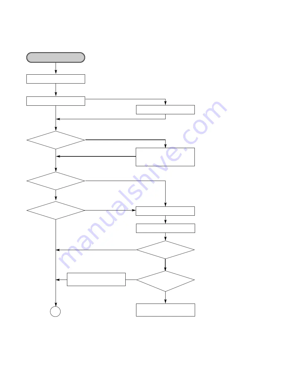
• Check the communication Iines
between IC203 and IC201.
• Check and replace that.
Writing Part Check.
Does the unit
becomes stand-by mode to
record/dubbing?
YES
NO
Eject Tray.
Go to “ALPC Logic Circuit Check”.
Dose Writing finish
without any error?
YES
NO
NO
Go to “BETA Measurement
Circuit Check”.
Check the connection of IC201
pin 187 and replace IC201.
Is the written file
read nomally?
Is the re-written file
readed nomally?
Is
ROPCSH input signal
Pulse when CD-R writing
(IC301 pin 38)
YES
YES
Refer “Laser is abnormal”.
Load tray with CD-R/RW Disc.
Start Recording or dubbing.
OK
YES
Summary of Contents for CDR 26
Page 28: ...28 IC403 IC403 2 8 IC402 ...
Page 47: ......
Page 51: ...6 436 079 441 076 441 071 080 2 072 436 072A 072A A08 ...
Page 71: ...71 UIT BOARD DIAGRAMS TOP SIDE LOCATION GUIDE ...
Page 72: ...72 IN P C BOARD BOTTOM SIDE LOCATION GUIDE ...
Page 73: ...TOP SIDE ARD LOCATION GUIDE 4 I O P C BOARD BOTTOM SIDE 73 ...
Page 74: ...74 GRAM UIT DIAGRAM ...
Page 75: ...75 RAM ...
Page 76: ...76 ...
Page 77: ...77 GRAM ...
Page 78: ...78 M ...
Page 79: ...79 ...
Page 80: ...80 ...


