P R E L I M I N A R Y R E L E A S E
3 9
Component Audio System
Harman Kardon
Festival 60/80
European MW (AM) ADJUSTMENT Festival 60/80 (TUNER UNIT)
Adjustment Item
MW (AM) Adjustment
Condition
Set the Function selector to the “MW” position.
Equipment
DIGITAL VOLT METER
AM SIGNAL GENERATOR and LOOP ANTENNA
2 CHANNEL VOLT METER
OSCILLOSCOPE
AM ANTENA COIL
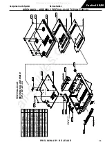
See Fig.1 and Fig.4
on page XX
Connection and Set Up
INPUT:
AM ANTENNA TERMINAL
For OSC and IF: Input 603kHz(400Hz, 30% modulation), 282uV/m(49dBuV/m)
to the Loop Antenna of a Unit.
For Tracking: Input 999kHz(400Hz, 30% moidulation), 159uv/m(44dBuV/m) to the Loop
Antenna of a Unit.
OUTPUT:
JP203(-) and JP204(+) for Frequency Range adjustment.
Lch/Rch output(LCN251) Inter Frequency and Tracking adjustment.
See Fig.1 and Fig.4
on page XX
Adjustment Point
1.
MW OSC of RF215 (Black core) for Frequency Range.
2.
T231 for IF(Inter Frenquency).
3.
MW ANT. Coil of RF215 (Yellow core) for Tracking.
Adjustment Method
1. Frequency Range
Set the tuning frequency of unit to 603Hz.
Adjust RF215 (Black core) so that leading of DC VOLT METER reads 1.9
±
0.1V
2. IF
Set the tuning frequency of unit to 999kHz.
Adjust T231 so that output level reads maximum.
3. Trackng
Adjust RF215 (Yellow core) so that output level reads maximum.
European LW (AM) ADJUSTMENT Festival 60/80 (TUNER UNIT)
Adjustment Item
LW (AM) Adjustment
Condition
Set the Function selector to the “LW” position.
Equipment
DIGITAL VOLT METER
AM SIGNAL GENERATOR and LOOP ANTENNA
2 CHANNEL VOLT METER
OSCILLOSCOPE
AM ANTENA COIL
See Fig.1 and Fig.4
on page XX
All manuals and user guides at all-guides.com


