FUNCTION DESCRIPTION
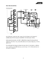
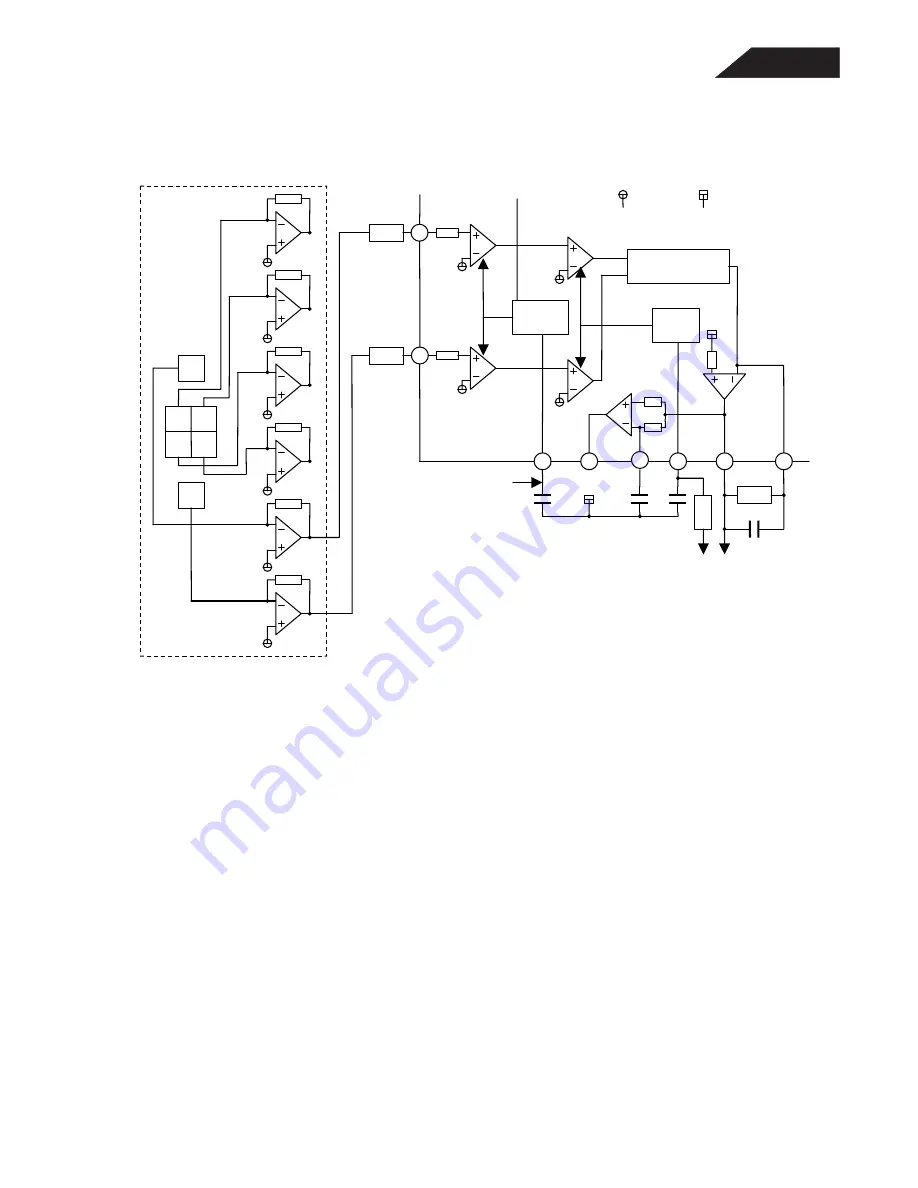
Tracking System
The tracking error output of E and F is given to Pin 25 (TEOUT). C8 is required for
oscillation-proof. R10 is chosen such that TEOUT of Pin 25 become 1.4Vp-p.
During alignment procedure, the DSP IC (MN662790) will adjust the tracking balance
voltage V
TBAL
from Pin 31. V
TBAL
varies with reference to the center voltage V
REF2
(=1.65 V)
within
±
0.5 V.
The tracking gain will change according to the type of disc. For normal disc or CDR disc,
V
GCTRL
is set to V
REF2
; for CDRW disc V
GCTRL
is set to V
REF2
- 0.75 V. At the same time, the
focus gain is changed too.
A B
C D
F
PDIC
E
32
31
28
21
30
23
25
24
GCTRL
To Focus System
TBAL
Subtraction
R10
TEN
C8
TEOUT
V
GCTRL
C2
C15
C5
R5
V
REF1
V
REF2
R15
R14
V
TBAL
17
FL8380
Summary of Contents for FL 8380
Page 21: ...FL8380 ...
Page 22: ...FL8380 ...
Page 23: ...FL8380 ...
Page 24: ...FL8380 ...
Page 25: ...FL8380 ...
Page 27: ...FL8380 27 ...
Page 28: ...FL8380 28 ...
Page 29: ...FL8380 29 ...
Page 30: ...FL8380 30 ...
Page 31: ...FL8380 31 ...
Page 32: ...FL8380 32 ...
Page 54: ...Motor driver IC BA6209 BA6209N Measurement circuit FL8380 54 ...
Page 59: ...FL8380 59 ...
Page 60: ...FL8380 60 ...
Page 68: ...FL8380 68 ...
Page 69: ...FL8380 69 ...
Page 70: ...FL8380 70 ...
Page 71: ...FL8380 71 ...


