background image

Each precaution in this manual should be followed during servicing.

Components identified with the IEC symbol

in the parts list are special significance to safety. When replacing a component identified with

, use only the replacement parts designated, or parts with the same ratings or resistance, wattage, or voltage that are designated in the

parts list in this manual. Leakage-current or resistance measurements must be made to determine that exposed parts are acceptably

insulated from the supply circuit before retuming the product to the customer.

Some semiconductor (solid state) devices can be damaged easily by static electricity. Such components commonly are called

Electrostatically Sensitive (ES) Devices. Examples of typical ES devices are integrated circuits and some field effect transistors and

semiconductor "chip" components.

The following techniques should be used to help reduce the incidence of component damage caused by static electricity.

1. Immediately before handling any semiconductor component or semiconductor-equipped assembly, drain off any electrostatic charge on

your body by touching a known earth ground. Alternatively, obtain and wear a commercially available discharging wrist strap device,

which should be removed for potential shock reasons prior to applying power to the unit under test.

2. After removing an electrical assembly equipped with ES devices, place the assembly on a conductive surface such as aluminum foil, to

prevent electrostatic charge build-up or exposure of the assembly.

3. Use only a grounded-tip soldering iron to solder or unsolder ES devices.

4. Use only an anti-static solder removal device. Some solder removal devices not classified as "anti-static" can generate electrical charges

sufficient to damage ES devices.

5. Do not use freon-propelled chemicals. These can generate electrical change sufficient to damage ES devices.

6. Do not remove a replacement ES device from its protective package until immediately before you are ready to install it. (Most replacement

ES devices are packaged with leads electrically shorted together by conductive foam, aluminum foil or comparable conductive material.)

7. Immediately before removing the protective material from the leads of a replacement ES device, touch the protective material to the

chassis or circuit assembly into which the device will be installed.

Be sure no power is applied to the chassis or circuit, and observe all other safety precautions.

8. Minimize bodily motions when handling unpackaged replacement ES devices. (Otherwise harmless motion such as the brushing together

or your clothes fabric or the lifting of your foot from a carpeted floor can generate static electricity sufficient to damage an ES devices.

CAUTION :

AVR330      


   harman/kardon 


Summary of Contents for NOCTURNE 330

Page 1: ...FUNCTIONS 10 TROUBLESHOOTING GUIDE 14 PROCESSOR RESET 14 DISASSEMBLY 15 BULLETIN HK2003 10 16 TECH TIP HKTT2004 03 18 TECH TIP HKTT2003 01 22 UNIT EXPLODED VIEW 23 BLOCK DIAGRAM 24 AMP BIAS ADJUSTMEN...

Page 2: ...or to applying power to the unit under test 2 After removing an electrical assembly equipped with ES devices place the assembly on a conductive surface such as aluminum foil to prevent electrostatic c...

Page 3: ...l overlays control shaft etc Plug the AC line cord of the appliance directly into a 120V AC 60Hz outlet and turn the AC power switch on Any current measured must not exceed o 5mA ANY MEASUREMENTS NOT...

Page 4: ...Section Television Format NTSC Input Level Impedance 1Vp p 75 ohms Output Level Impedance 1Vp p 75 ohms Video Frequency Response Composite and S Video 10Hz 8MHz 3dB Video Frequency Response Component...

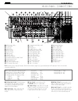
Page 5: ...g room See pages 17 and 20 22 for more information on speaker setup and configuration 7 Surround Mode Group Selector Press this but ton to select the top level group of surround modes Each press of th...

Page 6: ...udio devices video game consoles or other products that have a coax digital audio jack Video 4 Video Input Jacks These jacks may be used for temporary connection to the composite or S Video output of...

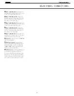
Page 7: ...inals are color coded in conformance with the CEA standards as follows Front Left White Front Right Red Center Green Surround Left Blue Surround Right Gray Surround Back Left Brown Surround Back Right...

Page 8: ...make certain that these holes are not blocked and that there is at least three inches of open space between the vent holes and any wooden or fabric surface It is normal for the fan to remain off at m...

Page 9: ...e such as a DVD recorder or PVR to these jacks Video 3 Audio Video Inputs Connect the com posite video and L R analog audio PLAY OUT jacks of a VCR or other video source to these jacks Tape Inputs Con...

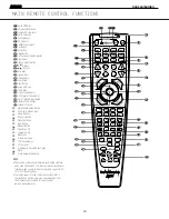
Page 10: ...own 39 TV Video Selector 40 SPL Selector 41 6 Channel 8 Channel Direct Input 42 Mute 43 EzSet Sensor Microphone NOTE The function names shown here are each button s feature when used with the AVR 330...

Page 11: ...l brightness regardless of the setting This is to remind you that the AVR is still turned on i Test Button Press this button to begin the sequence used to calibrate the AVR 330 s output levels See pag...

Page 12: ...ed in the remote See page 35 for more information on storing and recalling macros Disc Skip Button This button has no direct function for the AVR 330 but is most often used to change to the next disc...

Page 13: ...een selected When the AVR 330 remote is being programmed to operate another device this button is pressed with the Input Selector Button e to begin the programming process See page 35 for more informa...

Page 14: ...t or antenna away from computers fluorescent lights motors or other electrical appliances Letters flash in the channel indicator Digital audio feed paused Resume play for DVD display and digital audio...

Page 15: ...MAIN PCB INPUT PCB TRANS FORMER FRONT PCB 1 REMOVAL OF TOP COVER 2 REMOVAL OF FRONT PANEL DISASSEMBLY TUNER MODULE 3 PRINCIPAL PARTS LOACTION VIDEO PCB AVR330 harman kardon 15...

Page 16: ...er knobs make sure the jaws are insulated to avoid knob damage 3 Remove the 10 Phillips screws holding the front panel ass y to the chassis 6 at the bottom and 4 at the sides 4 Cut all plastic cable t...

Page 17: ...REQUIRED AVR330 AN0008 01000 to AN0008 08524 Volume control may not track accurately when turned erratic operation Change VR74 Rotary encoder AVR330 AN0008 08525 and above Modified By Factory NONE REQ...

Page 18: ...roblems Reset List can be found in this service manual 2 Print the block diagram from the service manual 3 With no inputs or speakers attached to the AVR turn on the receiver and turn the volume all t...

Page 19: ...the analog signal flow from the input jacks to the output jacks 11 If the output levels are the same check the power out stage at the speaker out jacks 12 If you find the levels at the speaker out jac...

Page 20: ...5 SW 7 8 10 10 9 5 7 11 AVR320 520 8 C H I N I C 5 0 1 I n I C 5 0 1 O u t C N 4 0 8 I C 7 0 4 I n I C 7 0 4 O u t I C 7 0 5 I n I C 7 0 5 O u t I C 7 0 6 I n I C 7 0 6 O u t I C 7 1 4 I n I C 7 1 4 O...

Page 21: ...UB 2 4 4 2 3 SBL 21 19 21 23 5 7 13 SBR 8 10 4 2 3 1 11 AVR230 330 6 c h i n I C 2 3 I n I C 2 3 O u t I C 2 6 I n I C 2 6 O u t I C 4 2 I n I C 4 2 O u t I C 4 I n I C 4 4 O u t I C 4 3 I n I C 4 3 O...

Page 22: ...tor CEGT B473J 0J0 AVR300 C906 Front PCB 0 1Farad 5 5v capacitor J4433210421X or P10791 ND AVR500 C906 Front PCB 0 1Farad 5 5v capacitor J4433210421X or P10791 ND AVR110 210 310 510 AVR120 220 320 520...

Page 23: ...AVR330 EXPLODED VIEW 23...

Page 24: ...ue Aug 26 21 18 51 2003 AVR330 harman kardon 24...

Page 25: ...ETER Connect to CN81 CN82 CN83 CN84 CN85 CN86 CN87 NO Channel Adjust for Adjustment 1 Front Left 25 92mV 5 VR83 CN82 VR86 2 Front Right 25 92mV 5 25 92mV 5 25 92mV 5 25 92mV 5 VR84 CN86 VR82 3 Center...

Page 26: ...AVR330 harman kardon...

Page 27: ...AVR330 harman kardon 27...

Page 28: ...AVR330 harman kardon...

Page 29: ...AVR330 harman kardon...

Page 30: ...CAM350 PRO V 7 6 Mon Sep 01 10 29 56 2003 Untitled 30 AVR330 harman kardon...

Page 31: ...M350 PRO V 7 6 Mon Sep 01 10 59 10 2003 Untitled AVR330 harman kardon 31...

Page 32: ...HCEA1VH100T CAP ELECT 10UF 35V C736 HCBS1H223ZFT CAP CERAMIC 0 022UF 50V Z C737 HCBS1H180JT CAP CERAMIC 18PF 50V C738 HCBS1H180JT CAP CERAMIC 18PF 50V C770 HCBS1H223ZFT CAP CERAMIC 0 022UF 50V Z C771...

Page 33: ...0V ZF C866 HCEA1CKS100T CAP ELECT 10UF 16V C867 HCEA1CKS100T CAP ELECT 10UF 16V C868 HCEA1CKS470T CAP ELECT 47UF 16V C869 HCEA1CKS470T CAP ELECT 47UF 16V C870 HCBS1H681KBT CAP CERAMIC 680PF 50V C871 H...

Page 34: ...26 HVTKRC107MT TRANSISTOR NPN KRC107M Q727 HVTKRC107MT TRANSISTOR NPN KRC107M Q728 HVTKRC107MT TRANSISTOR NPN KRC107M Q729 HVTKRC107MT TRANSISTOR NPN KRC107M Q731 KVTKSA1175YT TRANSISTOR NPN KSA1175Y...

Page 35: ...OHM 1 5W J R733 CRD20TJ272T RES CARBON 2 7K OHM 1 5W J R734 CRD20TJ103T RES CARBON 10K OHM 1 5W J R735 CRD20TJ103T RES CARBON 10K OHM 1 5W J R736 CRD20TJ272T RES CARBON 2 7K OHM 1 5W J R737 CRD20TJ10...

Page 36: ...5W J R832 CRD20TJ562T RES CARBON 5 6K OHM 1 5W J R833 CRD20TJ102T RES CARBON 1K OHM 1 5W J R834 CRD20TJ102T RES CARBON 1K OHM 1 5W J R835 CRD20TJ184T RES CARBON 180K OHM 1 5W J R836 CRD20TJ184T RES C...

Page 37: ...OHM 1 5W J R900 CRD20TJ104T RES CARBON 100K OHM 1 5W J R901 CRD20TJ152T RES CARBON 1 5K OHM 1 5W J R902 CRD20TJ152T RES CARBON 1 5K OHM 1 5W J R903 CRD20TJ102T RES CARBON 1K OHM 1 5W J R904 CRD20TJ10...

Page 38: ...B905080EN WIRE ASS Y BN90 CWB2B902090EN WIRE ASS Y BN94 KJP13GB99ZM CONNECTOR MOLEX35237 1310 BN95 KJP08GB99ZM CONNECTOR HOUSING MOLEX35237 0810 CN10 KJP04GB46ZM WAFER MOLEX 53015 CN11 KJP15GA98ZM WAF...

Page 39: ...LECT 100UF 16V C564 HCEA1CH101T CAP ELECT 100UF 16V C565 HCEA1CH101T CAP ELECT 100UF 16V C566 HCEA1CH101T CAP ELECT 100UF 16V C567 HCEA1CH101T CAP ELECT 100UF 16V C568 HCEA1CH101T CAP ELECT 100UF 16V...

Page 40: ...0V J C911 HCEA1CH471T CAP ELECT 470UF 16V C912 HCEA1CH221T CAP ELECT 220UF 16V C913 CCFT1H104ZF CAP SEMICONDUCTOR 0 1UF 50V ZF C914 HCQI1H473JZT CAP MYLAR 0 047UF 50V J C917 HCQI1H473JZT CAP MYLAR 0 0...

Page 41: ...3T 77 D583 HVD1SS133MT DIODE 1SS133T 77 D584 HVD1SS133MT DIODE 1SS133T 77 D585 HVD1SS133MT DIODE 1SS133T 77 D601 HVD1SS133MT DIODE 1SS133T 77 D801 HVD1SS133MT DIODE 1SS133T 77 D802 HVD1SS133MT DIODE 1...

Page 42: ...HVTKTC3200GRT TRANSISTOR NPN KTC3200GR Q565 HVTKTC3200GRT TRANSISTOR NPN KTC3200GR Q601 HVTKTA1268GRT TRANSISTOR PNP KTA1268GR Q602 HVTKTA1268GRT TRANSISTOR PNP KTA1268GR Q603 HVTKTA1268GRT TRANSISTOR...

Page 43: ...BT TRANSISTOR NPN MUTE KTC2874B Q973 HVTKTC2874BT TRANSISTOR NPN MUTE KTC2874B Q991 HVTKRC107MT TRANSISTOR NPN KRC107M Q992 HVTKRA107MT TRANSISTOR NPN KRA107M Q993 HVTKRA107MT TRANSISTOR NPN KRA107M Q...

Page 44: ...1T RES CARBON 470 OHM 1 5W J R523 CRD20TJ471T RES CARBON 470 OHM 1 5W J R524 CRD20TJ471T RES CARBON 470 OHM 1 5W J R525 CRD20TJ471T RES CARBON 470 OHM 1 5W J R531 CRD20TJ221T RES CARBON 220 OHM 1 5W J...

Page 45: ...OHM 1 5W J R597 CRD20TJ561T RES CARBON 560 OHM 1 5W J R598 CRD20TJ561T RES CARBON 560 OHM 1 5W J R599 CRD20TJ561T RES CARBON 560 OHM 1 5W J R600 CRD20TJ561T RES CARBON 560 OHM 1 5W J R601 CRD20TJ223T...

Page 46: ...OHM 1 5W J R696 CRD25TJ470T RES CARBON 47 OHM 1 4W J R697 CRD25TJ470T RES CARBON 47 OHM 1 4W J R698 CRD25TJ470T RES CARBON 47 OHM 1 4W J R699 CRD25TJ470T RES CARBON 47 OHM 1 4W J R700 CRD25TJ470T RES...

Page 47: ...R823 KRD25FJ180T RES CARBON 18 OHM 1 4W F R824 KRD25FJ180T RES CARBON 18 OHM 1 4W F R830 CRD20TJ223T RES CARBON 22K OHM 1 5W J R831 CRD20TJ223T RES CARBON 22K OHM 1 5W J R832 CRD20TJ223T RES CARBON 22...

Page 48: ...F R922 CRD25TJ470T RES CARBON 47 OHM 1 4W J R924 CRD20TJ473T RES CARBON 47K OHM 1 5W J R925 CRD20TJ473T RES CARBON 47K OHM 1 5W J R926 CRD20TJ473T RES CARBON 47K OHM 1 5W J R927 CRD20TJ473T RES CARBON...

Page 49: ...CRD20TJ102T RES CARBON 1K OHM 1 5W J R987 CRD20TJ561T RES CARBON 560 OHM 1 5W J R988 CRD20TJ562T RES CARBON 5 6K OHM 1 5W J R989 CRD20TJ333T RES CARBON 33K OHM 1 5W J R991 CRD20TJ822T RES CARBON 8 2K...

Page 50: ...FER MOLEX 5267 02A CN91 KJP03GA89ZM WAFER MOLEX35328 0310 CN92 KJP02GA01ZM WAFER MOLEX 5267 02A CN94 KJP13GA98ZM WAFER MOLEX35336 1310 CN95 KJP08GA98ZM WAFER MOLEX35336 0810 ET01 CNE75 PLATE EARTH ET0...

Page 51: ...226 HCUS1H221JA CAP CHIP 220PF C233 HCUS1H181JA CAP CHIP 180PF C234 HCUS1H471JA CAP CHIP 470PF C235 HCUS1H223KC CAP CHIP 0 022UF C236 HCUS1H223KC CAP CHIP 0 022UF C241 HCUS1H181JA CAP CHIP 180PF C242...

Page 52: ...022UF C416 HCUS1H223KC CAP CHIP 0 022UF C417 HCUS1H223KC CAP CHIP 0 022UF C418 HCUS1H223KC CAP CHIP 0 022UF C419 HCUS1H223KC CAP CHIP 0 022UF C420 HCUS1H223KC CAP CHIP 0 022UF C423 HCUS1H151JA CAP CHI...

Page 53: ...UF ZF 1608 SIZE C775 HCUS1E104ZF CAP CHIP 0 1UF ZF 1608 SIZE C777 HCUS1H473ZF CAP CHIP 0 047UF C779 HCUS1E104ZF CAP CHIP 0 1UF ZF 1608 SIZE C780 HCUS1E104ZF CAP CHIP 0 1UF ZF 1608 SIZE C783 HCUS1H473Z...

Page 54: ...F 35V C408 HCEA1VH100T CAP ELECT 10UF 35V C409 HCEA1VH100T CAP ELECT 10UF 35V C410 HCEA1VH100T CAP ELECT 10UF 35V C426 HCQI1H182JZT CAP MYLAR 1800PF 50V J C431 HCEA1CH101T CAP ELECT 100UF 16V C432 HCE...

Page 55: ...TE1 IC40 HVITC9459F I C VOLUME TC9459F IC41 HVITC9459F I C VOLUME TC9459F IC42 HVITC9459F I C VOLUME TC9459F IC43 HVITC9459F I C VOLUME TC9459F IC44 HVITC9459F I C VOLUME TC9459F IC45 HVINJM2068MDTE1...

Page 56: ...R211 HRJ10DJ471T RES CHIP 470 OHM R212 HRJ10DJ471T RES CHIP 470 OHM R213 HRJ10DJ471T RES CHIP 470 OHM R214 HRJ10DJ471T RES CHIP 470 OHM R215 HRJ10DJ471T RES CHIP 470 OHM R216 HRJ10DJ471T RES CHIP 470...

Page 57: ...1608 SIZE R272 HRJ10DJ472T RES CHIP 1 10W 4 7K OHM J 1608 SIZE R273 HRJ10DJ101T RES CHIP 1 10W 100 OHM J 1608 SIZE R274 HRJ10DJ101T RES CHIP 1 10W 100 OHM J 1608 SIZE R275 HRJ10DJ472T RES CHIP 1 10W 4...

Page 58: ...00 OHM J 1608 SIZE R340 HRJ10DJ101T RES CHIP 1 10W 100 OHM J 1608 SIZE R341 HRJ10DJ122T RES CHIP 1 2K OHM R342 HRJ10DJ122T RES CHIP 1 2K OHM R343 HRJ10DJ122T RES CHIP 1 2K OHM R344 HRJ10DJ122T RES CHI...

Page 59: ...5 6K OHM R416 HRJ10DJ103T RES CHIP 10K OHM R417 HRJ10DJ562T RES CHIP 5 6K OHM R418 HRJ10DJ562T RES CHIP 5 6K OHM R419 HRJ10DJ562T RES CHIP 5 6K OHM R420 HRJ10DJ562T RES CHIP 5 6K OHM R423 HRJ10DJ122T...

Page 60: ...T RES CHIP 1 10W 100 OHM J 1608 SIZE R730 HRJ10DJ1R0T RES CHIP 1 OHM R731 HRJ10DJ1R0T RES CHIP 1 OHM R732 HRJ10DJ183T RES CHIP 18K OHM R733 HRJ10DJ4R7T RES CHIP 1608 SIZE R734 HRJ10DJ330T RES CHIP 1 1...

Page 61: ...ER YD200 SERIES JK11 CJJ4R019W TERMINAL IN OUT JK12 CJJ4P014W JACK IN OUT JK13 CJJ4P014W JACK IN OUT JK14 CJJ4R019W TERMINAL IN OUT JK15 CJJ4R037W JACK BOARD JK16 CJJ4N034Z JACK IN OUT JW21 CWE7202090...

Page 62: ...A1CH101T CAP ELECT 100UF 16V C450 HCBS1H223ZFT CAP CERAMIC 0 022UF 50V Z C451 HCEA1CH101T CAP ELECT 100UF 16V C452 HCBS1H223ZFT CAP CERAMIC 0 022UF 50V Z C453 HCEA1CH101T CAP ELECT 100UF 16V C454 HCBS...

Page 63: ...1UF 50V ZF C707 CCKT1H101KB CAP CERAMIC 100PF 50V KB C708 HCEA1CKS101T CAP ELECT 100UF 16V C709 CCFT1H104ZF CAP SEMICONDUCTOR 0 1UF 50V ZF C710 CCCT1H270JC CAP CERAMIC 27PF 50V JC C711 HCEA1CH101T CAP...

Page 64: ...IC47 HVINJM2137MTE1 I C NJM2137MTE1 IC51 HVILC74763M I C OSD LC74763M IC52 HVI74ACT04MTR I C HEX IC61 HVIHCF4053M013T I C S T IC62 HVINJM2581MTE1 I C NJM2581MTE1 IC71 HVITC74HCU04AFN IC INVERTER TC74H...

Page 65: ...W J R450 CRD20TJ102T RES CARBON 1K OHM 1 5W J R451 CRD20TJ102T RES CARBON 1K OHM 1 5W J R452 CRD20TJ102T RES CARBON 1K OHM 1 5W J R453 CRD20TJ332T RES CARBON 3 3K OHM 1 5W J R454 CRD25TJ562T RES CARBO...

Page 66: ...4 CRD20TJ750T RES CARBON 75 OHM 1 5W J R605 CRD20TJ750T RES CARBON 75 OHM 1 5W J R606 CRD20TJ750T RES CARBON 75 OHM 1 5W J R607 CRD20TJ750T RES CARBON 75 OHM 1 5W J R608 CRD20TJ750T RES CARBON 75 OHM...

Page 67: ...010Z JACK BOARD JK61 CJJ4L004Z JACK Y PB PR JK71 HJSTORX179L MODULE OPTICAL RX TORX179L JK72 HJSTORX179L MODULE OPTICAL RX TORX179L JK73 CJJ4S022Z JACK BOARD JK74 HJSTOTX179L MODULE OPTICAL TX TOTX179...

Page 68: ...BON 330 OHM 1 5W J R880 CRD20TJ331T RES CARBON 330 OHM 1 5W J R882 CRD20TJ122T RES CARBON 1 2K OHM 1 5W J R883 CRD20TJ122T RES CARBON 1 2K OHM 1 5W J R884 CRD20TJ122T RES CARBON 1 2K OHM 1 5W J R885 C...

Page 69: ...50V J C924 HCQI1H104JZT CAP MYLAR 0 1UF 50V J C107 CCKT1H103ZF CAP CERAMIC 0 01UF 50V ZF C108 CCKT1H103ZF CAP CERAMIC 0 01UF 50V ZF C109 CCFT1H104ZF CAP SEMICONDUCTOR 0 1UF 50V ZF C110 CCFT1H104ZF CA...

Page 70: ...NOB ROTARY AVR130 230 330 KGB1A111X BADGE HARMAN KARDON KGX1A338MBC22 CAP VOLUME AVR130 230 330 CGL1A222 INDICATOR VOLUME AVR130 230 330 CGU1A317X WINDOW FIP AVR330 CGU1A318Z ORNAMENT VOLUME AVR130 23...

Page 71: ...LY ASS Y F904 KJCFC5S HOLDER FUSE F905 KJCFC5S HOLDER FUSE F906 KJCFC5S HOLDER FUSE F907 KJCFC5S HOLDER FUSE CMY1A218 HEAT SINK TR AVR130 230 330 CTB3 8J SCREW F901 KBA2D2500TLET FUSE F902 KBA2D2500TL...

Page 72: ...HIFTER 2 1 2 1 3 4 2 5 6 3 7 4 1 2 1 3 4 2 5 6 3 7 4 1 3 4 5 6 7 8 9 10 14 28 11 12 13 27 26 25 24 23 22 21 20 19 18 17 16 15 LATCH CIRCUIT SHIFT REGISTER LEVEL SHIFTER LATCH CIRCUIT L S R S Vss GND V...

Page 73: ...AVR330 harman kardon 73...

Page 74: ...AVR330 harman kardon 74...

Page 75: ...AVR330 harman kardon 75...

Page 76: ...LC74763 74763M Pin Assignment Serial Data Input Timing No 5039 4 19 Top view AVR330 harman kardon 76...

Page 77: ...625 command switch During output functions as general output port or character data output command switch Low 525 lines high 625 lines NTSC PAL switch input output Switches the color mode between NTSC...

Page 78: ...No 5039 5 19 System Block Diagram LC74763 74763M AVR330 harman kardon 78...

Page 79: ...3 RX0 42 AVSS 41 VCOM 40 R 39 AVDD 38 TVDD 13 NC 14 TX0 15 TX1 16 BOUT 17 18 UOUT 19 VOUT 20 DVDD 21 DVSS 22 MCKO1 23 36 35 34 33 32 31 30 29 28 27 26 INT0 OCKS0 CSN CAD0 OCKS1 CCLK SCL CM1 CDTI SDA C...

Page 80: ...DIT TX0 Error Detect STATUS INT1 Q subcode buffer TX1 B C U VOUT 8 to 3 VIN Serial Control Mode Input Selector Clock Recovery Clock Generator DAIF Decoder AC 3 MPEG Detect DEM Audio I F X tal Oscillat...

Page 81: ...Serial Select Pin L Serial Mode H Parallel Mode 10 XTL0 I X tal Frequency Select 0 Pin 11 XTL1 I X tal Frequency Select 1 Pin 12 VIN I V bit Input Pin for Transmitter Output 13 TVDD I Input Buffer Po...

Page 82: ...ip Address 0 Pin in Serial Mode IIC H 36 INT0 O Interrupt 0 Pin 37 INT1 O Interrupt 1 Pin 38 AVDD I Analog Power Supply Pin 3 3V 39 R External Resistor Pin 18k 1 resistor should be connected to AVSS e...

Page 83: ...2dB Amp S4 S3 S6 S7 20K 20K 20K 13 Vin1 V V SW2 SW1 Vout1 Vout2 Vout3 SW4 BLOCK DIAGAM NJM2296M IC41 42 43 SW3 GND SW5 Vin2 Vin3 Vin4 Vin5 1 15 11 16 10 14 12 2 9 7 5 4 6 8 3 20K 20K 20K 20K 20K 75 d...

Page 84: ...AVR330 harman kardon 84...

Page 85: ...S R COM R S R S R COM R S R S R COM DATA CK LEVEL SHIFTER 2 1 2 3 1 4 5 6 2 7 8 3 1 2 3 1 4 5 6 2 7 8 3 1 3 4 5 6 7 8 9 10 14 28 11 12 13 27 26 25 24 23 22 21 20 19 18 17 16 15 LATCH CIRCUIT SHIFT REG...

Page 86: ...AVR330 harman kardon 86...

Page 87: ...AVR330 harman kardon 87...

Page 88: ...XIN XOUT RESETB P2 7 TAOUT P2 6 TACAP P2 5 TACK P3 6 TCOUT1 P2 4 TBOUT P3 4 T1OUT0 P1 0 P1 7 P0 0 P0 7 AVREF AVSS Port 3 P3 0 P3 7 Port 4 P4 0 P4 7 INT0 INT7 Port 5 P5 0 P5 7 Port 6 P6 0 P6 7 SIO UAR...

Page 89: ...9 48 47 46 45 44 43 42 41 1 2 3 4 5 6 7 8 9 10 11 12 13 14 15 16 17 18 19 20 61 62 63 64 65 66 67 68 69 70 71 72 73 74 75 76 77 78 79 80 21 22 23 24 25 26 27 28 29 30 31 32 33 34 35 36 37 38 39 40 P3...

Page 90: ...output mode selected by software input or push pull output Software assignable pull up D 72 65 P2 0 P2 7 I O Bit programmable port input or output mode selected by software input or push pull output S...

Page 91: ...elected by software input or push pull output Software assignable pull up Alternately P5 0 P5 3 can be used as I O for serial por UART0 UART1 respectively G 22 17 11 9 TxD1 RxD1 TxD0 RxD0 P6 0 P6 7 O...

Page 92: ...r A D 3 P2 5 TACAP I Capture input pins for timer A D 2 P2 6 TAOUT O Pulse width modulation output pins for timer A D 1 P2 7 TBPWM O Carrier frequency output pins for timer B D 4 P2 4 TCOUT0 TCOUT1 O...

Page 93: ...T2 PA1 OUT1 PA0 OUT0 P97 IN1 P96 IN0 P95 PPG5 P94 PPG4 P93 FRCK ADTG CS3 P92 SCK1 CS2 P91 SOT1 CS1 P90 SIN1 CS0 P87 IRQ7 P86 IRQ6 P85 IRQ5 P84 IRQ4 P83 IRQ3 P82 IRQ2 MD2 80 79 78 77 76 75 74 73 72 71...

Page 94: ...pins function as the external data bus high output pins 99 100 1 2 1 to 4 P20 to P23 E CMOS H This is a general purpose I O port When the bits of external address output control register HACR are set...

Page 95: ...This is a general purpose I O port A04 In non multiplex mode this pin functions as an external address pin BIN1 8 16 bit up down counter input pin channel 1 13 15 P35 E CMOS H This is a general purpos...

Page 96: ...xternal bus mode this pin functions as the lower data write strobe output WRL pin When the WRE bit in the EPCR regis ter is set to 0 this pin functions as a general purpose I O port 71 73 P53 D CMOS T...

Page 97: ...hese are the analog input pins 41 to 44 43 to 46 P64 to P67 H CMOS These are general purpose I O ports AN4 to AN7 These are the analog input pins 25 27 P70 G CMOS H This is a general purpose I O port...

Page 98: ...When the A D converter is in use this pin functions as the external trigger input pin CS3 Chip select 3 60 62 P94 D CMOS This is a general purpose I O port PPG4 PPG timer output pin 61 63 P95 D CMOS T...

Page 99: ...U04AFN IC71 72 76 LOGIC SYMBOL TRUTH TABLE 1 2 3 4 5 6 7 1A 1Y 2A 2Y 3A 3Y GND 6A 6Y 5A 5Y 4A 4Y Vcc 14 13 12 11 10 9 8 A L H Y H L 1A 1 3 5 9 11 13 2A 3A 4A 5A 6A 1Y 2Y 3Y 4Y 5Y 6Y 2 4 6 8 10 12 AVR3...

Page 100: ...AVR330 harman kardon 100...

Page 101: ...nterface Framer Shifter Input Buffer Controller PIN ASSIGNMENT CS493263 TOP VIEW BlOCK DIAGRAM CS493263 VD1 DGND1 AUDATA3 XMT958 WR DS EMWR GPIO10 RD R W EMOE GPIO11 A1 SCDIN A0 SCCLK DATA7 EMAD7 GPIO...

Page 102: ...input sample rate clock pin 27 CMPDAT SDI I PCM audio data input number 2 pin 28 CMPCLK BICK I PCM audio input bit clock pin 29 CREQ LRCK I PCM audio input sample rate clock pin 30 CLKIN XIN I Master...

Page 103: ...Order Number Package Number Package Description 74AC04SC M14A 14 Lead Small Outline Integrated Circuit SOIC JEDEC MS 120 0 150 Narrow Body 74AC04SJ M14D 14 Lead Small Outline Package SOP EIAJ TYPE II...

Page 104: ...lable o Channel Independent Digital De emphasis for 32 44 1 48kHz sampling o Zero Detect function o Channel Independent Digital Attenuator with soft transition 3 Speed mode o Soft Mute o 3 wire Serial...

Page 105: ...PDN 8 BICK 9 MCLK 10 DVDD ROUT1 47 LOUT2 46 45 44 ROUT2 43 LOUT3 42 LOUT3 41 ROUT3 40 ROUT3 39 LOUT4 38 SDTI4 13 SDTI1 14 SDTI2 15 SDTI3 16 LRCK 17 18 CCLK SCL 19 CDTI SDA 20 CSN CAD1 21 DCLK 22 DSDL4...

Page 106: ...L CDTI 3 wire Serial I2C H SDA I2 C Bus CSN CAD1 I Chip Select Pin I2C L CSN 3 wire Serial I2C H CAD1 I2 C Bus DCLK I DSD Clock Pin DSDL1 I DAC1 DSD Lch Data Input Pin DSDR1 I DAC1 DSD Rch Data Input...

Page 107: ...ing Single ended Input Digital HPF for DC Offset cancel S N D 96dB 5V for 48kHz DR 106dB 5V for 48kHz S N 106dB 5V for 48kHz Sampling Rate Ranging from 4kHz to 96kHz Master Clock 256fs 384fs 512fs 768...

Page 108: ...VD DGND AINR AINL AGND VA Top View 8 7 6 5 4 3 2 1 9 10 11 12 13 14 15 16 DIF PDN LRCK MCLK SCLK CKS2 CKS0 SDTO Compatibility with AK5380 AK5380 AK5381 Master Mode Not Available Available HPF OFF Not...

Page 109: ...z 8 DGND Digital Ground Pin 9 SDTO O Audio Serial Data Output Pin L Output at Power down mode 10 LRCK I O Output Channel Clock Pin L Output in Master Mode at Power down mode 11 MCLK I Master Clock Inp...

Page 110: ...o SYMBOL NAME AND FUNCTION 11 10 9 A B C Binary Control Inputs 6 INH Inhibit Inputs 12 13 2 1 5 3 IN OUT ax ay bx by cx cy Input Output 14 OUT IN ax or ay 15 OUT IN bx or by 4 OUT IN cx or cy 7 VEE Su...

Page 111: ...AVR330 harman kardon 111...

Page 112: ...AVR330 harman kardon 112...

Page 113: ...MAIN BOARD 1 AMP AVR330 harman kardon 113...

Page 114: ...MAIN BOARD 1 AMP AVR330 harman kardon 114...

Page 115: ...MAIN BOARD 1 AMP AVR330 harman kardon 115...

Page 116: ...VIDEO BOARD AVR330 harman kardon 116...

Page 117: ...VIDEO BOARD AVR330 harman kardon 117...

Page 118: ...VIDEO BOARD AVR330 harman kardon 118...

Page 119: ...FRONT BOARD AVR330 harman kardon 119...

Page 120: ...FRONT BOARD AVR330 harman kardon 120...

Page 121: ...FRONT BOARD AVR330 harman kardon 121...

Page 122: ...MAIN BOARD 2 BIAS REGULATOR AVR330 harman kardon 122...

Page 123: ...INPUT BOARD 1 ANALOG AVR330 harman kardon 123...

Page 124: ...INPUT BOARD 1 ANALOG AVR330 harman kardon 124...

Page 125: ...INPUT BOARD 1 ANALOG AVR330 harman kardon 125...

Page 126: ...INPUT BOARD 2 DIGITAL AVR330 harman kardon 126...

Page 127: ...INPUT BOARD 2 DIGITAL AVR330 harman kardon 127...

Page 128: ...INPUT BOARD 2 DIGITAL AVR330 harman kardon 128...

Page 129: ...WIRING DIAGRAM AVR330 harman kardon 129...

Page 130: ...6 SET 5 SNOW PAD L 3 HARTZONE2 HABAAAM1 5VHK CSA3A012Z REMOCON ASS Y ZONE2 AM LOOP ANTENNA ASS Y BATTERY 1 1 3 CARD WARRANTY CQE1A172X 1 SNOW PAD L AVR330 SET AVR330CCSET 1 INSTRUCTION MANUAL FM 1 PO...

Reviews: