


PT2500 rev (G) 10/23/96
Installation & Configuration
8
Although there are two outputs for the
center channel, only one connection is
typically required. As the two outputs are
identical, either one may be used and the
other left open.
Subwoofer connections are made using
the
SUBWOOFER Outputs
d
. When
using a powered subwoofer, connect
BOTH the left and right output subwoofer
outputs to the respective left and right
line level inputs on your subwoofer. As
the PT2500 subwoofer outputs are full
range, it will be necessary to adjust the
crossover frequency to your requirements
on the subwoofer’s control panel. Consult
the subwoofer instructions or consult
your dealer for additional information.
When using a single subwoofer and a
separate mono power amplifier the
PT2500 subwoofer outputs must be com-
bined using an optional “Y” adapter. If
there is no crossover in the subwoofer an
optional, external low pass filter or
crossover system must also be used.
When using the PT2500 with an external
5.1 digital audio decoder such as the
Harman Kardon ADP303, connect all
Channel Outputs
abc
to the
decoder’s inputs. Use an optional “Y”
adapter to combine the subwoofer out-
puts and connect the “Y” adapter to the
decoder’s subwoofer input. The outputs
of the digital audio decoder should then
be connected to your power amplifiers.
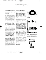
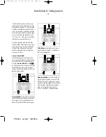
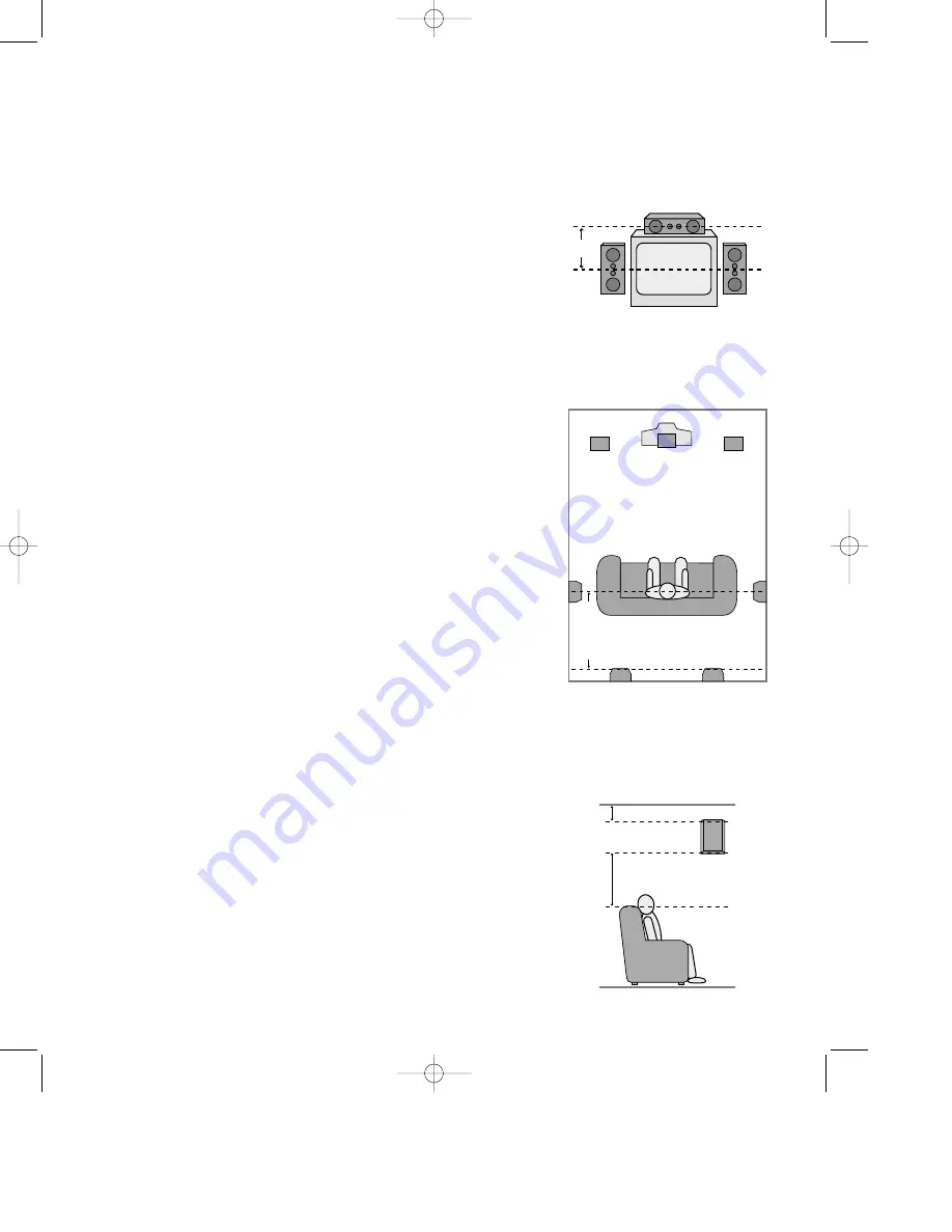
Speaker Selection and Placement
Depending on the type of center channel
speaker in use and your viewing device,
place the center speaker directly above or
below your TV .
Once the center channel speaker is
installed, position the left and right front
speakers so that they are as far away
from one another as the center channel
speaker is from the preferred listening
position. Ideally, the front channel
speakers should be placed so that their
tweeters are no more than 24
″
off center
from the tweeter in the center channel
speaker.
Depending on the specifics of your room
acoustics and the type of speakers in use,
imaging may be improved by moving the
front left and right speakers slightly for-
ward of the center channel speaker. If
possible, adjust all front loudspeakers so
that they are aimed at ear height when
you are seated in the listening position.
Using these guidelines, you may find that
it takes some experimentation to find the
correct location for the front speakers in
your particular installation. Don’t be
afraid to move things around until the
system sounds correct. Optimize speaker
locations so that pans across the front of
the room sound smooth, and that sounds
from all speakers appear to arrive at the
listening position at the same time with-
out delay from the center speaker as
opposed to the left and right speakers.
Surround speakers should be placed on
the side walls of the room, at or slightly
behind the listening position. The center
of the speaker should face into the room
with the speaker drivers pointing towards
the front and rear of the room. The
speakers should be located so that the
bottom of the cabinet is at least 24
″
higher than the listeners’ ears when in
the desired area.
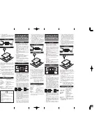
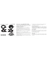
Right Front
Speaker
Left Front
Speaker
No more
than 24"
Center Front Speaker
A) Front Channel Speaker Installation
with Direct View TV Sets or Rear Screen
Projectors
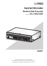
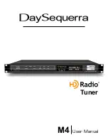
Center Front
Speaker
Optional Rear Wall Mounting
TV or Projection Screen
Right Front
Speaker
Left Front
Speaker
No more than 6 feet
when rear-mounted
speakers are used
At least 2 feet
At least 6 inches from ceiling
The distance between the left and right
speakers should be equal to the distance
from the seating position to the viewing
screen. You may also experiment with
placing the left and right speakers slightly
forward of the center speaker.
•PT2500(g).qx 10/23/96 7:36 AM Page 9