


Introduction and Safety Information
Unpacking and Installation
The carton and shipping materials used
to protect your new PT2500 during ship-
ment were specially designed to cushion
it from shock and vibration. We suggest
that you save the carton and packing
materials for use in shipping if you move
or should the unit ever need repair.
To minimize the size of the carton in
storage, you may wish to flatten it. This
is done by carefully removing any staples
that attach the carton flaps to one anoth-
er, and then slitting the tape covering the
seams. Fold the carton down to a more
two dimensional appearance. Packing
materials that cannot be collapsed
should be saved along with the carton in
a plastic bag.
If you do not wish to save the packaging
materials, please note that the carton
and other sections of the shipping protec-
tion are recyclable. Please respect the
environment and discard those materials
at a local recycling center.
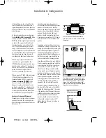
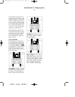
When positioning your PT2500 in its
final location, make certain that any
shelf or stand is capable of supporting it’s
weight, and that there is adequate venti-
lation on all sides, as well as on the top
and bottom. Do not place CDs, record
jackets, owner’s manuals, or other paper
on top of, or beneath the unit. This will
block air flow, causing degraded perfor-
mance and a possible fire hazard. If the
unit is to be enclosed in a cabinet or
rack, make certain that there is adequate
air circulation, with a means provided
for hot air to exit, and for cool air to be
brought in.
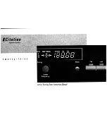
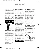
Using this Manual
For easy identification of the inputs, out-
puts and controls on the PT2500, a sepa-
rate reference card accompanies this
manual. Printed on that card are dia-
grams of the front and rear panels and
the remote control. Refer to that card as
needed to make certain that connections
are being made properly.
The following conventions are used
throughout this manual when referring
to the diagrams on the reference card:
1
: A number within a square references
a front panel control.
¡
: A number within a circle references
a connection point on the rear panel.
a
: A number within an oval references
a button on the remote control.
Example
: Bold type will be used to indi-
cate a front or rear panel control. It will
typically be followed with a reference let-
ter or number to the specific control
being described.
EXAMPLE
: OCR type indicates a mes-
sage that is visible through the display
window.
3
PT2500 rev (G) 10/23/96
•PT2500(g).qx 10/23/96 7:36 AM Page 4