1 5
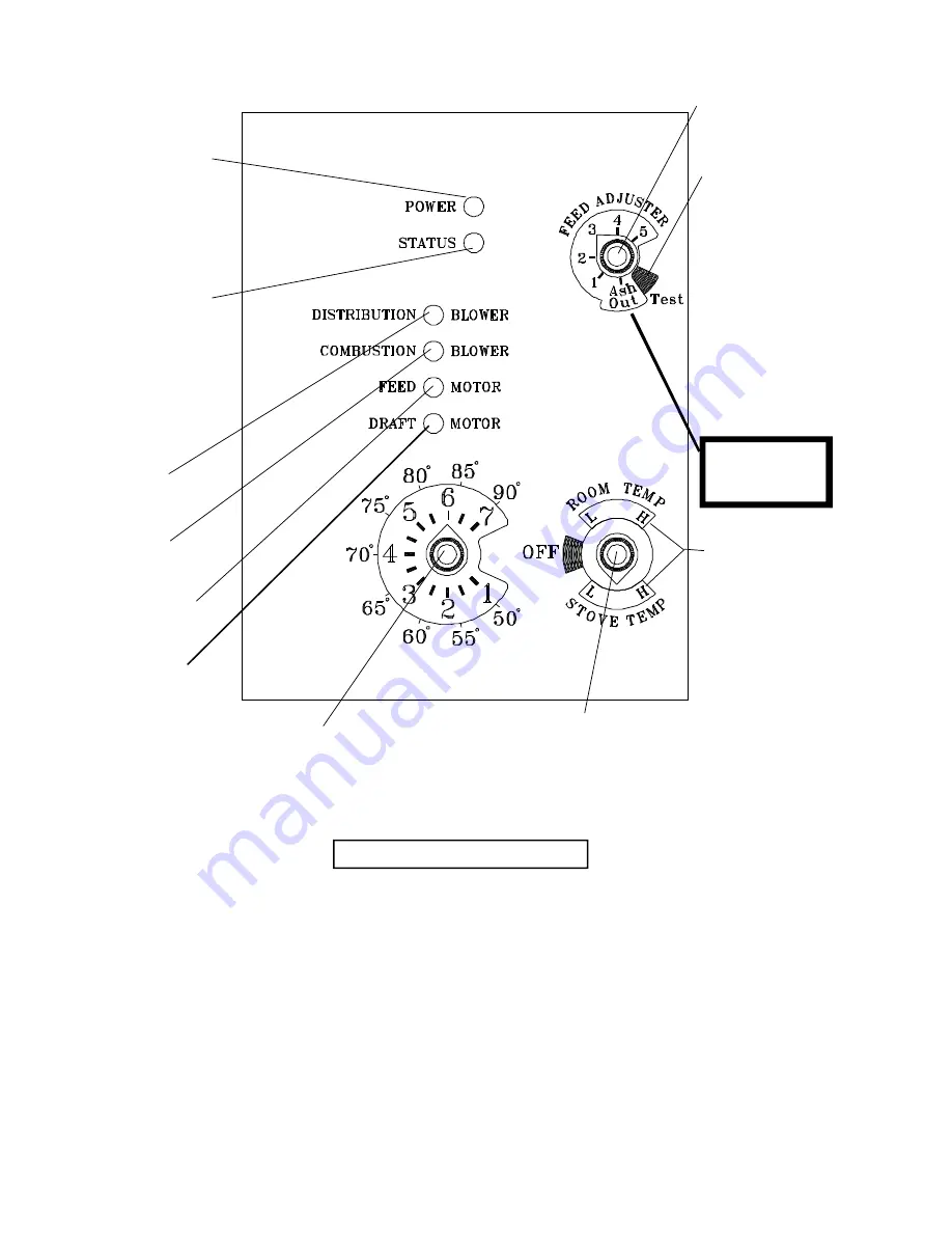
ESP CONTROL
Feed Adjuster
Sets the maximum feed
rate, 1 to 5
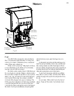
Test
Runs all motors at
full speed for two
minutes to check
operation. After two
minutes the stove will
go to minimum burn
and the blowers will
alternate from high
to low every two
minutes to remind
you that you are still
in "Test Mode".
Distribution Blower
speed adjustment range.
1 Blink:
Indicates control board self diagnostic
failure. This requires a Manual Reset*.
2 Blinks:
Indicates that the negative pressure in the
firebox has been too low for at least 68 seconds.
This begins a three stage shut-down process de-
scribed in detail on Page 30.
The most common cause of the 2 blink status is
leaving the ash door open for more than 3 to 5
minutes without turning the Feed Adjuster to "Ash
Out". For other causes of a 2 blink status see Page
29.
This requires a Manual Reset*.
3 Blinks:
Indicates ESP (Exhaust Sensing Probe)
failure. This requires a Manual Reset*.
4 Blinks:
Can occur only in Room Temp Mode
and indicates Room Sensing Probe failed or not
installed. If a Room Sensing Probe is then in-
stalled the status light will automatically reset.
NOTE: Only after unit has warmed up.
5 Blinks:
Indicates TCP (Temperature Control
Probe) failure. This requires a manual reset*.
* Manual Reset:
Disconnect power cord for a few
seconds and reconnect. If error still occurs call
your Dealer.
Temp Dial
Allows you to adjust the room temperature in
Room Temp Mode using the outer scale
marked in degrees Fahrenheit. It also allows
you to adjust the stove temperature while in
Stove Temp Mode using the inner scale
marked from 1 to 7.
Mode Selector
Allows you to choose between Room Temp
Mode, Stove Temp Mode, or OFF. Also
allows you to vary the Distribution
Blower speed by turning the knob to the
"high" or "low" side of each mode.
Power Light
Indicates power is "on" to
the control.
Indicates power to the
Feed Motor.
Indicates power to
Combustion Blower
Status Light
Will be lit in either Stove
or Room Temp Mode
when pointer is not within
"off" position band except
after normal shut down.
Blinks to indicate errors
listed below.
Indicates power to
Distribution Blower.
Ash Removal
position
See page 16
Operation:
Indicates power to the
Draft Motor.
Status Light Error Messages:
fig. 12
Summary of Contents for DVC500-C
Page 2: ...2 ...
Page 10: ...10 Installation Open ...
Page 12: ...12 Installation ...
Page 13: ...13 Installation ...
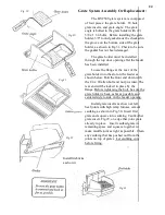
Page 16: ...16 ESP Control HopperLid Latch Ash Door Latch Handle GlassDoor Latch Handle Side Panel Latch ...
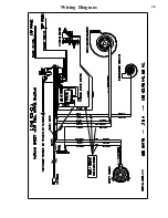
Page 26: ...26 Wiring Diagram ...