background image


11

#8


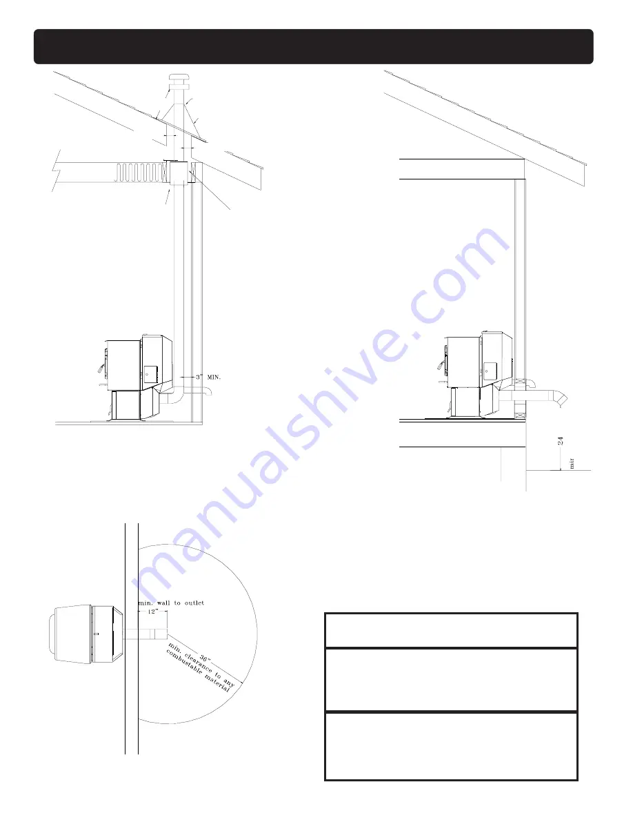
Installing


through


the


ceiling


vent

Through


the


ceiling


vent,


follow


PLvent

manufacturers


recommendations


when


using


wall

and


ceiling


pass


through.

Fig.


14

No


insulation


or

other


combustible

materials


are

allowed


within


3"

of


the


PL


vent


pipe.

PL


vent


manufacturer's

firestop


spacer


and


support

(See


Page


9


for

c o r n e r

i n s t a l l a t i o n

clearances)

Minimum


flue


vent

configuration

It


is


recommended


that

outside


air


be


installed


with


this

venting


configuration.

Min.


above


ground


level

18"

Storm


collar

Flashing

3"


min.

3"


min.

12"


min.

3"


min.

Fig.


15

Fig.


16

Venting

DO


NOT


INSTALL


A


FLUE


DAMPER


IN


THE

EXHAUST


VENTING


SYSTEM


OF


THIS


UNIT.

DO


NOT


CONNECT


THIS


UNIT


TO


A


CHIMNEY

FLUE


SERVING


ANOTHER


APPLIANCE.

INSTALL


VENT


AT


CLEARANCES


SPECIFIED

BY


THE


MANUFACTURER

CAUTION

DO


NOT


INSTALL


IN


SLEEPING


ROOM

WARNING

CAUTION

THE


STRUCTURAL


INTEGRITY


OF


THE

MOBILE


HOME


FLOOR,


WALL,


AND


CEILING/

ROOF


MUST


BE


MAINTAINED.

THE


STOVE


IS


HOT


WHILE


IN


OPERATION.

KEEP


CHILDREN,


CLOTHING


AND

FURNITURE


AWAY.


CONTACT


MAY


CAUSE

SKIN


BURNS.

Summary of Contents for P61-2

Page 1: ...LT FORYOUR SAFETY FOLLOW INSTALLATION DIRECTIONS CONTACT LOCAL BUILDING OR FIRE OFFICIALSABOUT RESTRICTIONSAND INSTALLATION INSPECTION REQUIREMENTS IN YOUR AREA CONTACT YOUR LOCAL AUTHORITY SUCH AS MUNICIPAL BUILDING DEPARTMENT FIRE DEPARTMENT FIRE PREVENTION BUREAU ETC TO DETERMINE THE NEED FORA PERMIT CETTEGUIDED UTILISATIONESTDISPONIBLEENFRANCAIS CHEZVOTRECONCESSIONNAIREDEHARMANSTOVE COMPANY SA...

Page 2: ...2 Fig 1 ...

Page 3: ... or even death SUITABLE FOR MOBILE HOME INSTALLATIONS SAVETHESEINSTRUCTIONS Harman Stove Company 352 Mountain House Road Halifax PA 17032 Testing Label 2 Assembly Installation 4 Venting 7 Operation 12 ESP Control 14 Maintenance 15 Trouble Shooting 18 Feeder Parts 19 Specifications 19 Wiring Diagram 20 Options 22 Parts List 23 Warranty 24 Table of Contents ...

Page 4: ... slide the covers outward as shown in the illustration To reinstall simply slide back into place and retighten the screws Firebrick Install the firebrick vertically on the angle above the burnpot Flame Guide Install the cast iron flame guide on top of the burnpot and make sure it is fully seated against the auger opening The bottom of the flame guide is marked 38 Rear Cover Panels Assembly and Ins...

Page 5: ...base plate 2 The unit must also be connected for the outside air See page 8 3 Floor protection and clearances must be followed as shown 4 Unit must be grounded to the metal frame of the mobile home CAUTION This appliance must be vented to the out side Due to high temperatures the stove should be placed out of traffic and away from furniture and draperies Children and adults should be alerted to th...

Page 6: ...e regula tor 1 I The clearance to service regulator vent outlet must be a minimum of 6 feet 1 J The clearance to a non mechanical air sup ply inlet to the building or the combustion air inlet to any other appliance must be a minimum of 48î 1 K The clearance to a mechanical air supply inlet must be a minimum of 10 feet 1 with outside air installed 6 feet L The clearance above a paved sidewalk or a ...

Page 7: ... of pipe lock together to form an air tight seal in most cases however in some cases a perfect seal is not achieved For this reason and the fact that the P61 operates with a positive vent pressure we specify that the joints also be sealed with clear silicone Outside Air Outside air is optional except in mobile homes and where building codes require The benefit of outside air is mainly noticed in s...

Page 8: ... natural draft in the event of a power failure 1 Preferred method This method provides excellent venting for nor mal operation and allows the stove to be installed closest to the wall Two inches from the wall is safe however four inches allows better access to remove the rear panel The vertical portion of the vent should be three to five feet high This vertical section will provide natural draft i...

Page 9: ... method 7 5 Installing into an existing fireplace chimney US only This method provides excellent venting for nor mal operation This method also provides natural draft in the event of a power failure The damper area must be sealed with a steel plate or fiberglass A cap should be installed on the chimney to keep out rain If the chimney condition is questionable you may want to install a liner all th...

Page 10: ...ealing system used by the manufacturer Pipe size should be increased to 4 using this method 7 Installing into an existing chimney US and Canada This method provides excellent venting for nor mal operation This method also provides natural draft in the event of a power failure In Canada and some places in the US it is re quired that the vent pipe extend all the way to the top of the chimney The pip...

Page 11: ...that outside air be installed with this venting configuration Min above ground level 18 Storm collar Flashing 3 min 3 min 12 min 3 min Fig 15 Fig 16 Venting DO NOT INSTALL A FLUE DAMPER IN THE EXHAUST VENTING SYSTEM OF THIS UNIT DO NOT CONNECT THIS UNIT TO A CHIMNEY FLUE SERVING ANOTHER APPLIANCE INSTALL VENT AT CLEARANCES SPECIFIED BY THE MANUFACTURER CAUTION DO NOT INSTALL IN SLEEPING ROOM WARNI...

Page 12: ... Dial to 7 This will allow the stove to burn at maximum for feed rate adjusting pur poses Apply starting gel to pellets in burn pot and light the gel Close the door after lighting At this point the distribution and combustion lights will be on and the feed motor light will be off As the tem perature of the fire increases the feed motor light will come on and pellets will feed into the burn pot As ...

Page 13: ... consumption is sac rificed for exact room temperature Therefore as it gets colder more pellets will be burned automati cally The distribution blower speed will vary accord ing to the position of the mode selector fig 21 Shut Down Procedure To kill the fire or stop burning the stove turn the Mode Selector to OFF This will cause the fire to diminish and burn out When the fire burns out and the stov...

Page 14: ...after unit has warmed up 6 Blinks Indicates that the control has calculated poor or incomplete combustion occurring for more than 50 minutes See Troubleshooting section for more details Manual reset disconnect power cord for a few seconds and reconnect If error still occurs call your Dealer Temp dial Allows you to adjust the Room temperature in Room Temp Mode using the outer scale marked in degree...

Page 15: ...han 25 feet from the unit or in another room are not recommended The room sensor is essential for the P61 s excel lent efficiency NOTE It is recommended that the room sensor be installed even if only installed on the rear of the unit as a return air sensor Fig 22 Room Sensor Installation Fig 23 Room Sensor and Rear Shield Installation Rear Shields 5 16 Hex Head Screws 2 on each side 5 16 Hex Head ...

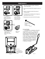
Page 16: ...ously Cleaning The stove will need to be cleaned for approxi mately every 2 to 5 tons of pellets burned The amount of pellets burned before cleaning will vary depending on the brand of pellets 1 Shut down stove and disconnect power cord to insure that all motors are stopped 2 Remove ash pan as described earlier 3 Remove combustion blower cover by turning the latch vertical as shown in Fig 26 and s...

Page 17: ... 31 11 Slide ash pan into stove and latch into place Fig 26 Fig 27 Fig 28 Fig 29 Fig 30 Fig 31 Brush not supplied Can be found in hardware stores Be careful not to damage ESP probe when cleaning with brush Soot and Fly Ash The products of combustion will contain small particles of fly ash The fly ash will collect in the exhaust venting system and restrict the flow of the flue gases Incom plete com...

Page 18: ...ve is not burning take the opportunity to scrape the burn pot to remove carbon buildup A vacuum cleaner is handy to remove the residue Be sure the stove is cold if you use a vacuum Carbon buildup can be scraped loose with the fire burning using the special tool provided with your stove Scrape the floor and sides of the burn pot The carbon will be pushed out by the incoming fuel Always wear gloves ...

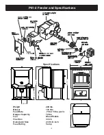
Page 19: ...5 cfm Feed Rate 75 to 7 5 lbs per hr Hopper Capacity 72 lbs Fuel Wood Pellets Flue Size 3 inch Outside Air Size 2 3 8 I D inch Fuse Rating 5 amp 32 375 9 23 5 34 5 5 250 12 375 Specifications 29 5 P61 2 Feeder and Specifications ...

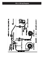
Page 20: ...20 P61 2 Wiring Diagram ...

Page 21: ...y slide the trim over the ash lip and into the groove on the trim Decorative Tile Decorative tile is available in several designs The tile installs behind the trim on the ash door Cleaning Plated Trim Gold or nickel plated hardware should never be buffed or polished Abrasive cleansers and metal polishes will remove the plating and therefore should never be used If the plating needs to be cleaned w...

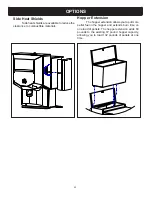
Page 22: ...o combustible materials Hopper Extension The hopper extension allows you to put more pellet fuel in the hopper and extends burn time on one load of pellets The hopper extension adds 60 pounds to the existing 72 pound hopper capacity allowing you to load 132 pounds of pellets at one time ...

Page 23: ...er Washer for Hopper Lid 3 31 90131101 Power Cord 3 20 29685 Manual Ignite Label Control Panel Door 3 90 05802 Fire Brick 3 3 40 900450125 White Black Control Knob 3 3 31 00605 Control Knob Shaft 3 3 31 00015 Front Glass 3 40 950133125 Burn Pot Gasket 2 3 44 00409 Tailpipe Gasket 3 44 06179 Wiring Diagram 3 89 06503 Control Panel Sticker 3 90 08646 Owner s Manual 3 90 05810 Hopper Lid Label 3 90 0...

Page 24: ... Damage and or repairs including but not limited to remote controls filters fuses knobs glass ceramic brick panels ceramic fiber afterburners door packing tile ce ramic log sets paint batteries or battery back up and related duct work are not covered Also excluded from this warranty are consumable or normal wear items including but not limited to flame guides grates coal bars afterburner hoods fir...

Reviews: