6
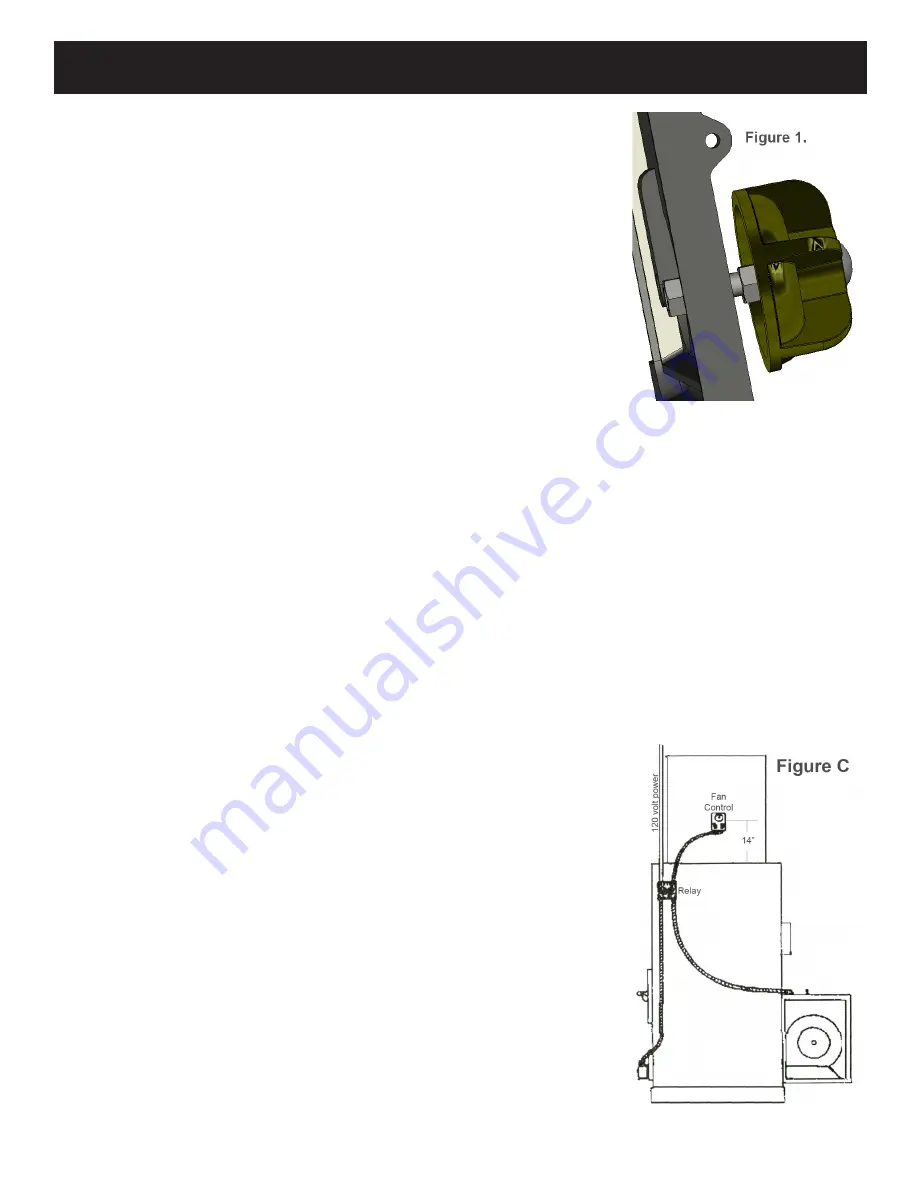
Bolt the auto-
matic draft control to
the bottom door. Be
sure to hold the unit
straight while tighten-
ing. After the auto-
matic draft control
is mounted, the two
wires must be strung
through the flexible
conduit and two fittings
supplied. The knockout
plug of the junction box
must be removed to in-
stall the conduit fitting.
Check the door of the
automatic draft control to assure proper operation.
warning:
Keep pieces of wood or coal out of the
draft door opening mechanism, as this could cause
the door to stick.
NOTE: Oil the hinge at the begining of the heating
season with a light oil.
The junction box is best mounted on the side
of the furnace about in. back and 8 in. from the top
of the sheet metal side. (fig. C or D) If this location is
inconvenient, anywhere on the right side will work.
SF1500, SF2500, SF3500.
This figure represents the models; SF1500,
SF500, and SF3500. It’s intention is to represent
the approximate location of the various controls.
This drawing may also be used as a recommenda-
tion for routing of the
wiring and approxi-
mate dimension of
control spacing.
Please note
that this drawing is for
reference only. Each
specific installation will
vary.
Furnace Installation
Installing wood/Coal high limit Switch-
SF600 only.
First, install the sheet metal sides as de-
scribed in the previous section. Install the snap disc
switch into the hole on the right side sheet metal.
Then mount the open backed junction box around
the snap switch. Proceed with wiring as shown on
page 0. Also refer to Figure D. in this section.
mounting The Oil burner-
SF600 only.
Remove oil burner unit from it’s box. Loosen
the four bolts in the pipe on the front of the furnace.
Insert the nose of the oil gun into the pipe. Before
sliding the oil burner all the way in, apply the gasket
around the nose of the oil gun by wrapping it around
the nose. Next, slide the oil burner into the pipe and
secure it by tightening the four bolts around the col-
lar. Be sure to tighten the bolts evenly to locate the
oil burner in the center of the pipe. The final set-up
of the oil burner should be done by an experienced
oil burner technician with the proper equipment. Re-
fer to the SF600 wiring diagram on page 0 and the
oil burner manual for proper burner set-up. There is
also a section at the end of this manual with specific
oil burner instructions.
venting guidelines.
Your Harman hot-air furnace must be vented
to it’s own separate flue-lined “Class A” chimney,
not less than 8” X 8” in size. The chimney must be
capable of providing a draft reading of at least .06”
water column on a draft meter, in order to function
properly. The Chimney must be a minimum of 6
ft. high, and must be two feet higher than anything
within 0 ft. The chimney must also be at least 3 ft.
higher than the point at which it exits or passes by
the roof. A barometric damper must be installed in
the flue to eliminate excessive draft. Any horizontal
sections of connector pipe must have at least /4 in.
per foot rise. Limit the number of elbows to two or
less. All joints in the connector pipe must be secured
with sheet metal screws.
Assembly.
Bolt the shaker handle to the block on the
lower left side of the furnace, using the bolts and
lock-washers provided.
Bolt the two manual draft controls to the
front load door. Proper installation allows the draft
controls to open approximately /” from the door
surface. See Figure .


