


10
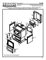
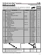
Harman TL300
venting
Chimney Connectors and Chimneys
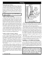
Draft
Draft is widely misunderstood. It is important that you,
the stove operator, realize that draft is a variable
effect
, not
a given quantity. Stoves and chimneys do not
have
draft, yet
draft is the key to your stove’s performance.
Draft is a force, produced by an operating stove and
the chimney to which it is attached. It is created by hot
gases rising up the chimney, creating a pressure difference
between the inside of your home and the outside air. It con-
tinually moves fresh combustion air into the stove, and hot
exhaust gases out of the stove; without this constant flow,
the fire will go out.
Other factors, such as barometric pressure, winds, the
tightness of the home, the total inside chimney volume,
chimney height and the presence of venting devices such
as exhaust fans also play a role in maintaining an adequate
draft. Low barometric pressures, super insulated homes,
and exhaust fans can reduce draft; winds can play havoc
with draft; and too large or too small a chimney volume
can cause reduced draft due to the excessive cooling or
not enough room to vent the exhaust gases. Introducing
outside air directly to the stove may help remedy a low
draft problem. Some signs of inadequate draft are smoking,
odor, difficulty in maintaining the fire, and low heat output.
Overdraft can be caused by a very tall chimney even if it
is the recommended size, and can cause overfiring of your
stove. Signs of an overdraft include rapid fuel consumption,
inability to slow the fire, and parts of the stove or chimney
connector glowing red. It is important that you follow the
chimney guidelines in this manual, including size, type, and
height to avoid draft problems.
When installed and operated according to this manual, the
TL300 will produce enough hot gases to keep the chimney
warm so that adequate draft is maintained throughout the
burn cycle.
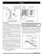
Chimney Connectors
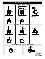
In general, following these guidelines will ensure compli-
ance with all national and provincial codes; prior to begin-
ning your installation, check with your local building code
official(s) regarding any additional local requirements or
regulations which may influence the design and placement
of your venting system.
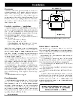
The Harman TL300 may be installed with (.6 mm) 24
gauge chimney connector pipe. The size of the connector
should correspond to the size of the flue collar opening. Do
not use makeshift components.
No part of the chimney connector may pass through an attic
or roof space, closet or other concealed space, or through a
floor or ceiling. Whenever possible, avoid passing the connec-
tor through a combustible wall; if you must, use an approved
wall pass-through, described later in this section.
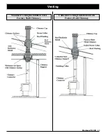
Assemble the connector beginning at the flue collar, with
the crimped ends pointing towards the stove (to keep debris
and creosote flakes inside the system). Each joint, including
the one to the stove’s flue collar and the one to the chimney
itself should be secured with at least three sheet metal screws.
Screws may be a maximum of 3 inches apart. A 1-1/4" (32
mm) overlap is required at each joint, including the flue collar
attachment. No more than two 90 degree elbows should be
used, and the total length of connector should not exceed 10
feet (3m) All horizontal runs of connector must have a mini-
mum upward slope of 1/4 inch per foot (20 mm per meter).
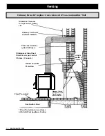
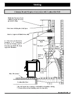
Wall Pass-thrus
Occasionally it is necessary to pass the chimney connector
through a combustible wall to reach the chimney. Depending
on your local building codes, and the pertinent provincial or
national codes, there are several choices for accomplishing
this safely. Before beginning your installation, contact local
officials, and also the chimney connector and chimney
manufacturer for specific requirements.
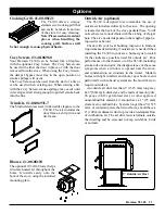
Canada.
Three methods are approved by the Canadian
Standards Association. The diagram shows one method
requiring an 18" (460 mm) air space between the connector
and the wall. It allows use of one or two covers as described in
the diagram. The other two methods are described in detail in
the current issue of CAN/CSA B365, the national standard.
United States
In the U.S., the national code is NFPA 211.
While many localities adopt this standard, be sure to check
with local authorities before beginning your installation.
The NFPA (National Fire Protection Association) permits
four methods for passing through a combustible wall. A
commonly used method to pass through a wall directly to a
masonry chimney is to clear a minimum 12"(305 mm) around
the entire chimney connector, and fill it with brick masonry
which is at least 3.5"(90 mm) thick. A fireclay liner, minimum
3/8" (9 mm) wall thickness must run through the brick wall
to the chimney liner (but not beyond the inner surface of the
liner). It must be cemented in place with refractory cement.
This method is illustrated. For details on the other three
options, refer to the most recent edition of the NFPA 211
code.
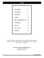
Summary of Contents for TL300
Page 2: ...2 Harman TL300 ...
Page 26: ...26 Harman TL300 This page intentionally left blank ...
Page 27: ......
Page 28: ......
Page 29: ...Harman TL300 29 Notes ...
Page 30: ...30 Harman TL300 Notes ...
Page 31: ......


