Harman® • Allure50 Installation Manual_R2 • 2016 - ___ • 09/16
21
3-90-888000i
5
Appliance Set-Up
A. Unpacking
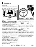
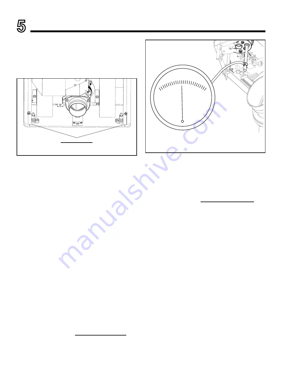
The Allure50 is bolted (1/4 x 1" hex head bolts) to the skid to
prevent movement during shipping.
To free the stove from the skid you must remove the hold-
down bolts from both the left and right hand side shipping
brackets using a 7/16” socket or wrench. Figure 5.1.
B. Firebox Draft and Combustion Fan RPM
These units are pre-tested at the factory with exactly 120 VAC,
60 Hz. They are checked and adjusted for firebox tightness,
gasket leakage, motor operation and igniter operation. The
Allure50 is then factory set at a mid-point adjustment and in
most cases will not need any adjustments.
Check and record the firebox draft before installing venting
and after venting is installed
(before starting fire)
.
There is a draft meter port located in the back of the unit at
the pressure switch where draft can be measured. Install the
magnahelic meter
(capable of at least .5” of water column)
Figure 5.2.
Connect the power cord to a 120 VAC, 60Hz grounded
receptacle. (A surge protector is recommended to protect
the circuit board.) Also be sure that the polarity of the outlet
that the stove is plugged into is correct.
Go to the “Home Screen”, the power icon should be gray.
Press menu, on the first menu page press “test” icon.
The test page has 4 component test modes. The second icon
is for the combustion fan test.
One press of the icon turns the combustion fan to full line
voltage.
(Note: During this test , the combustion fan will
not achieve its top RPM of 3200 due to the density of the
ambient air.)
All RPM displays could vary +/- 50 from that
of the set RPM’s. Allow several minutes for the fan motor to
warm up.
Press the icon a second time, the combustion fan will go
to “Maximum” (as set in the
Authorized Dealer Only
area
under the combustion fan icon)
The “Maximum” is factory set at 2900 RPM. Allow the RPM
to stabilize and record the firebox draft Maximum.
Before Install: __________ IWC
After Install: __________ IWC
(Firebox Draft and Combustion Fan RPM Cont.)
Press the icon a third time, the combustion fan will go to
“Minimum” (as set in the
Authorized Dealer Only
area
under the combustion fan icon) allow the RPM to stabilize
and record the firebox draft minimum.
Before Install: __________ IWC
After Install: __________ IWC
Cold Stove Draft:
2500 RPM
Low -.20 and -.25
2900 RPM
High -.45 and -.50
Leaving the test page will end any tests in progress and
goes back to whatever mode of operation it was set to on
the home page.
If the unit is not adjusted properly, it does not cause a safety
concern. If the unit is adjusted too high, only efficiency is lost.
If the unit is adjusted too low, the low draft pressure switch
will not allow the feed motor or the igniter to operate.
Figure 5.1
Shipping Bolts (4)
(2) Bolts are located on the front
and rear of the unit.
Figure 5.2
MAGNEHELIC
INCHES OF WATER
0
.10
.20
.30
.40
.50
The rear panel will need to be removed prior to installing the draft
meter to the barbed tee. Be sure to hold the barbed tee while
removing the plug cover. Replace plug cover after draft test.


